...
| Note |
|---|
Refer to the installation manuals for full details and instructions. |
| Table of Contents |
|---|
| Description | Thumbnail | Where used | PDF document | Recommended Size | Sketchfab Model | ||||||
|---|---|---|---|---|---|---|---|---|---|---|---|
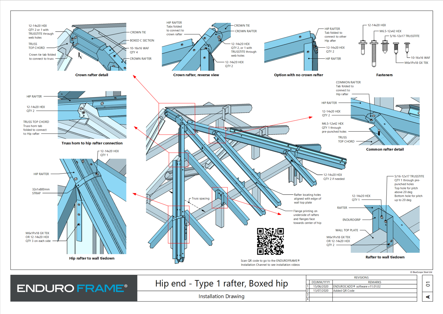
Hip End Installation - Type 1 Hip End |
| Site |
| A3 | |||||||
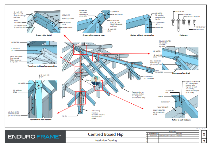
Hip End Installation- Type 1 Centred Boxed Hip |
| Site |
| A3 | |||||||
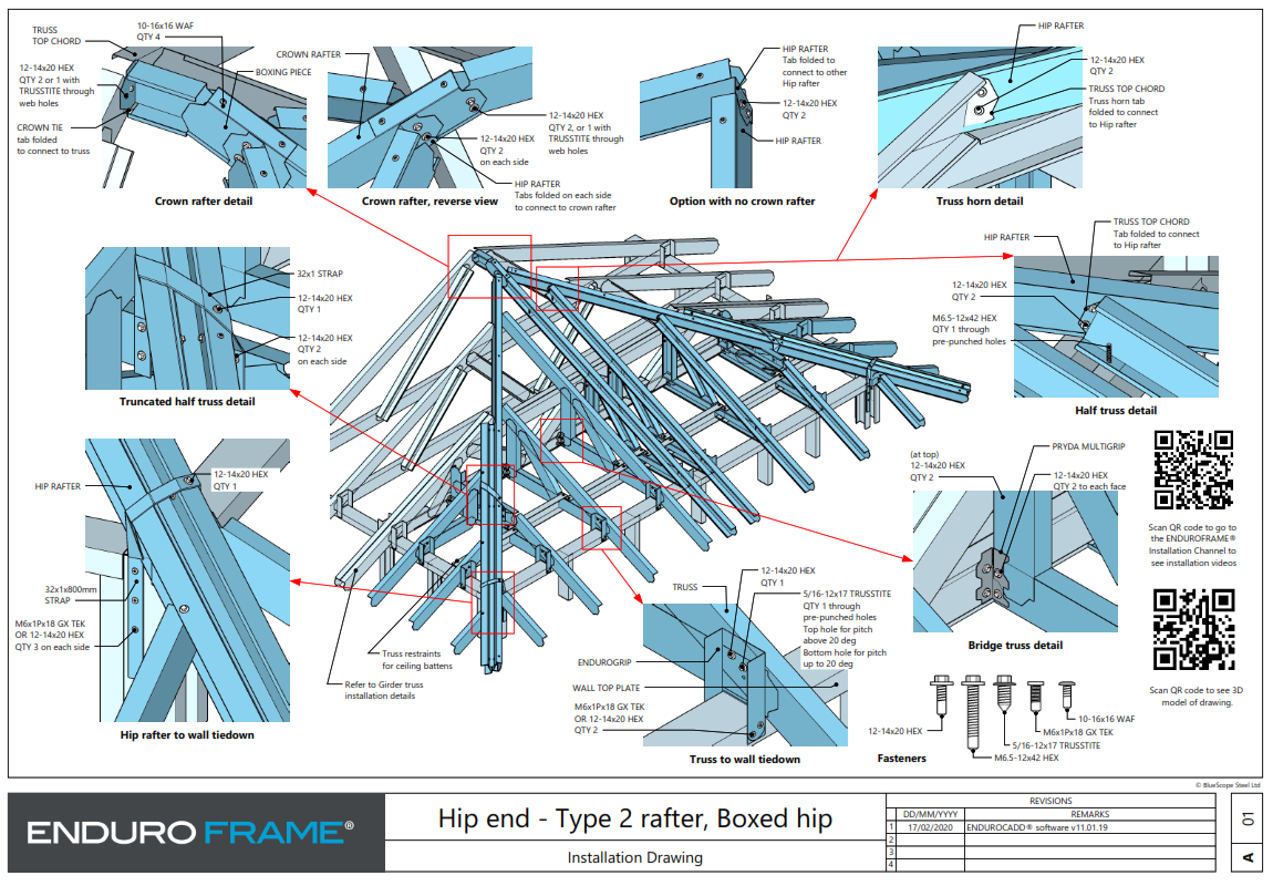
| Hip End Installation - Type 2 Hip End |
| Site |
| A3 | |||||||
Valley installation | 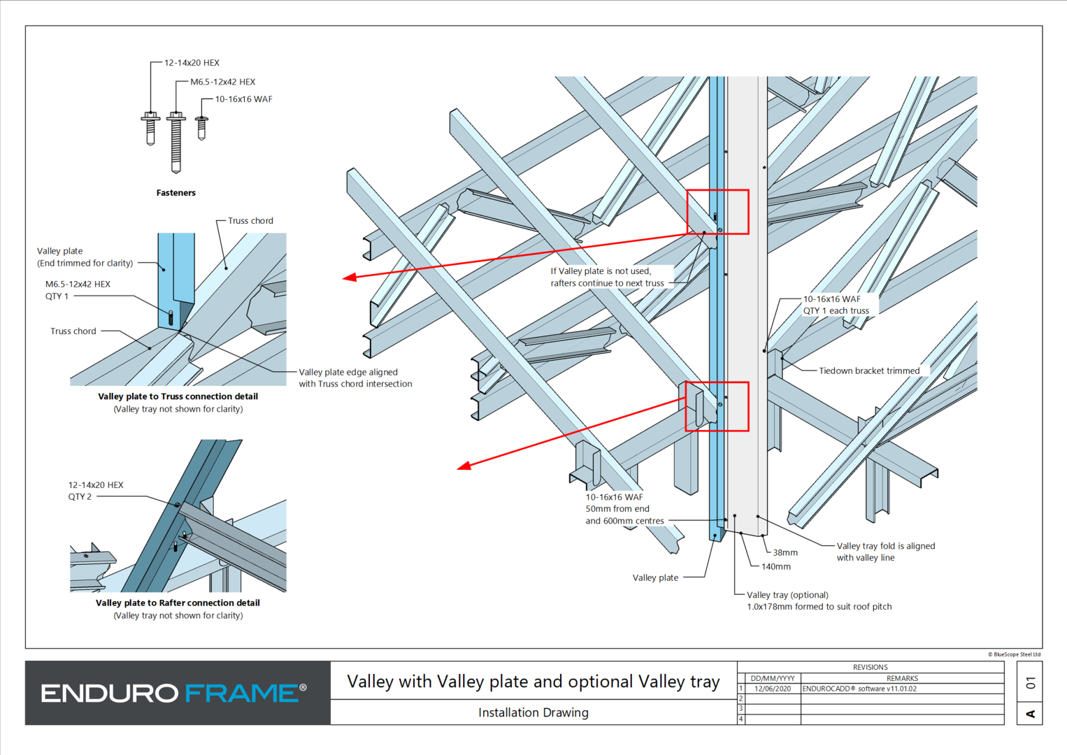 | Site |
| A3 | |||||||
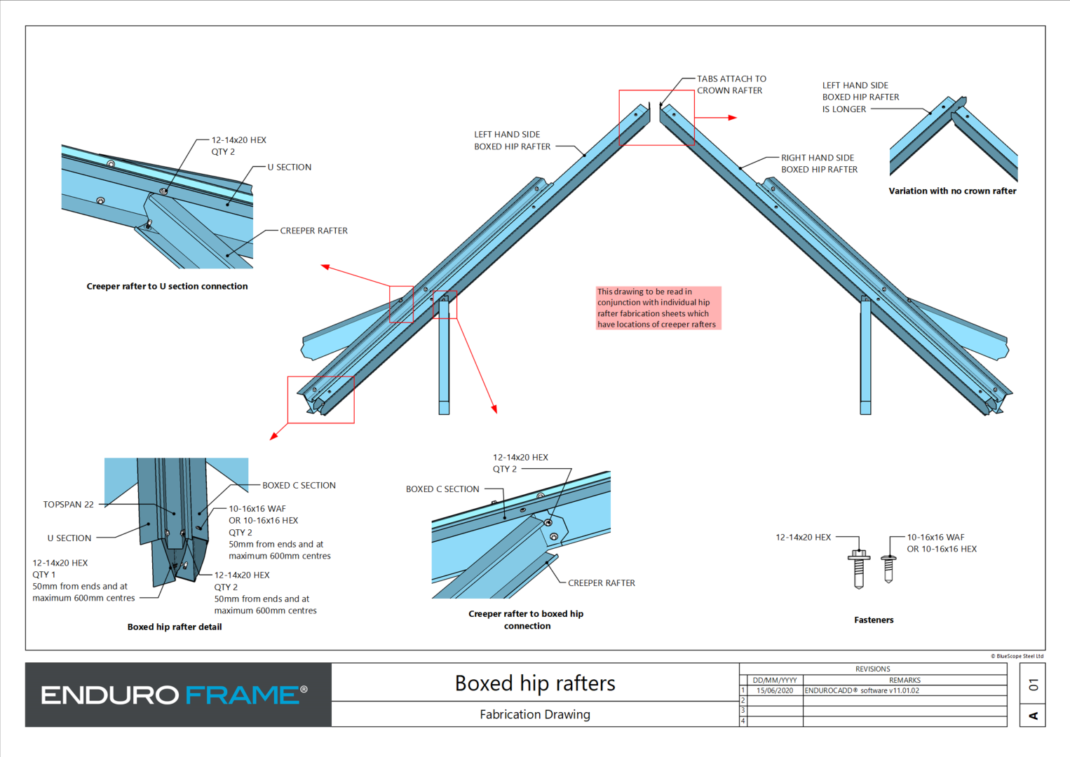
Boxed hip rafter fabrication |
| Factory |
| A3 | |||||||
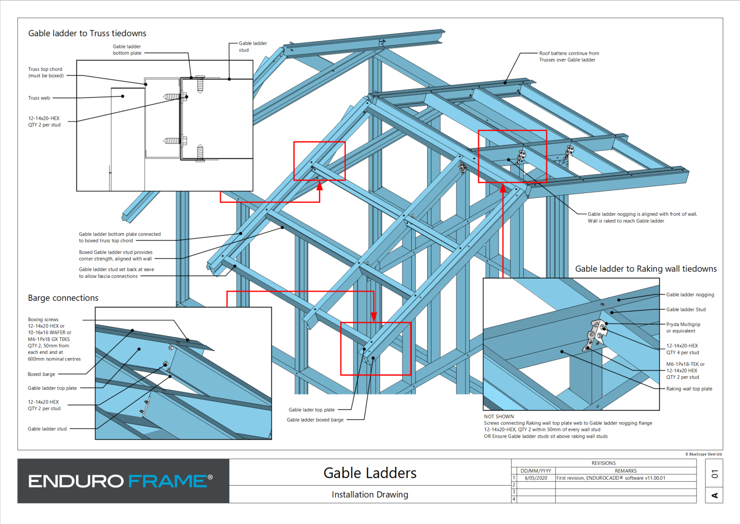
Gable ladder verges |
| Site |
| A3 | |||||||
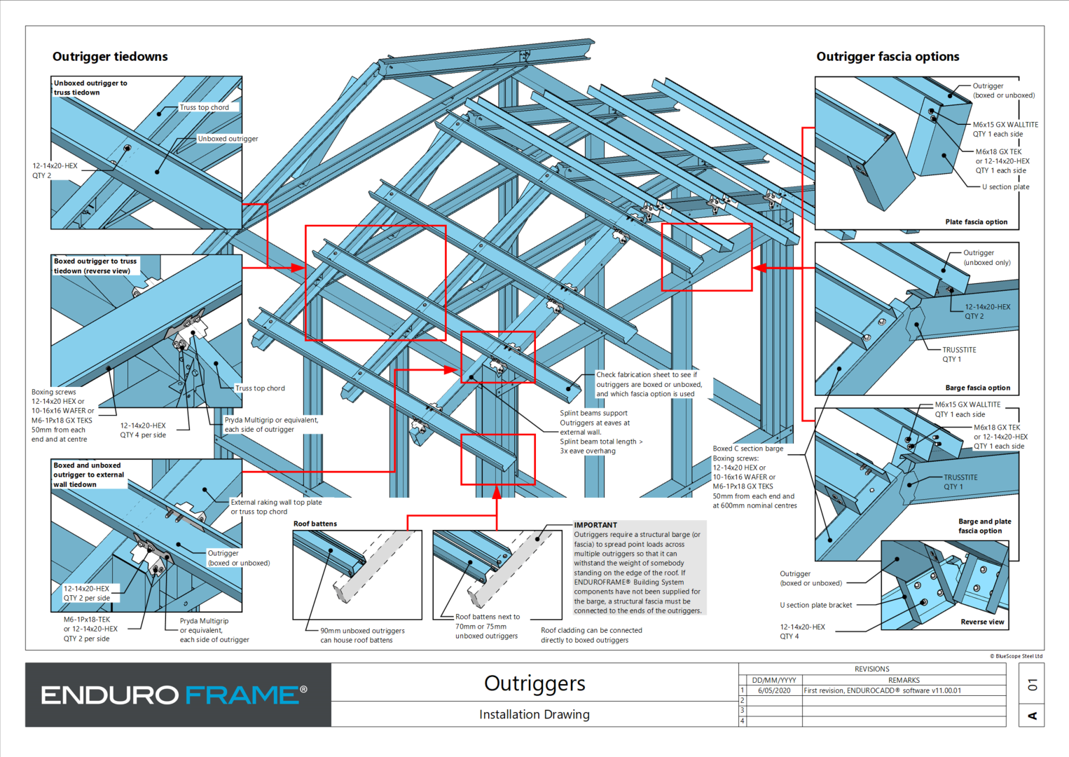
Outrigger verges |
| Site |
| A3 | |||||||
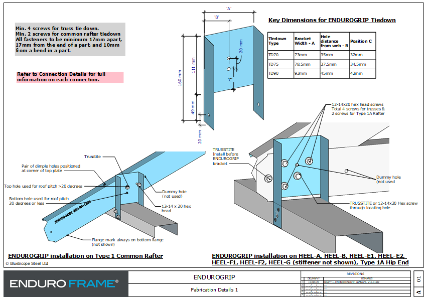
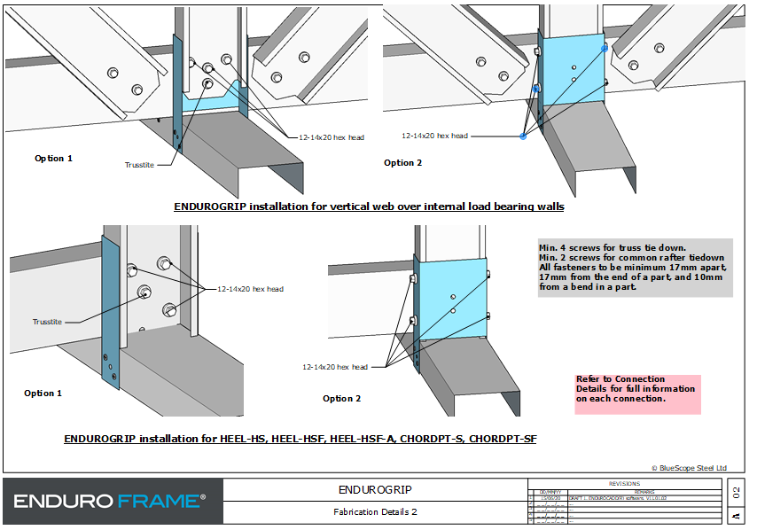
ENDUROGRIP Fabrication details - 2 pages |
| Site / Factory |
| A3 | |||||||
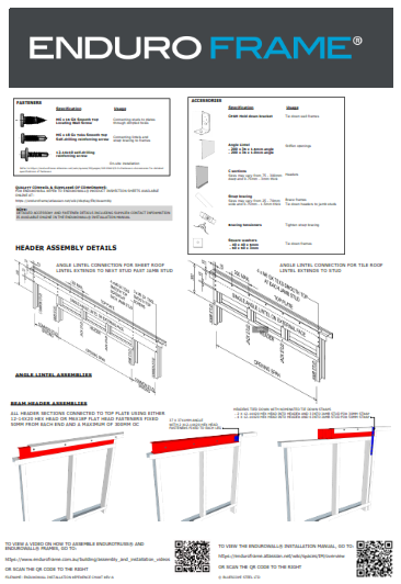
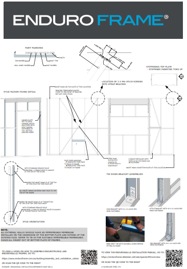
ENDUROWALL Fabrication Overview - 2 pages |
| Factory |
| A0 | |||||||
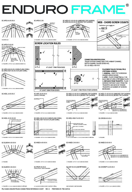
ENDUROTRUSS Connection Details Factory Poster |
| Factory |
| A0 | |||||||
ENDUROTRUSS General Assembly Instruction |
| Factory |
| A0 | |||||||
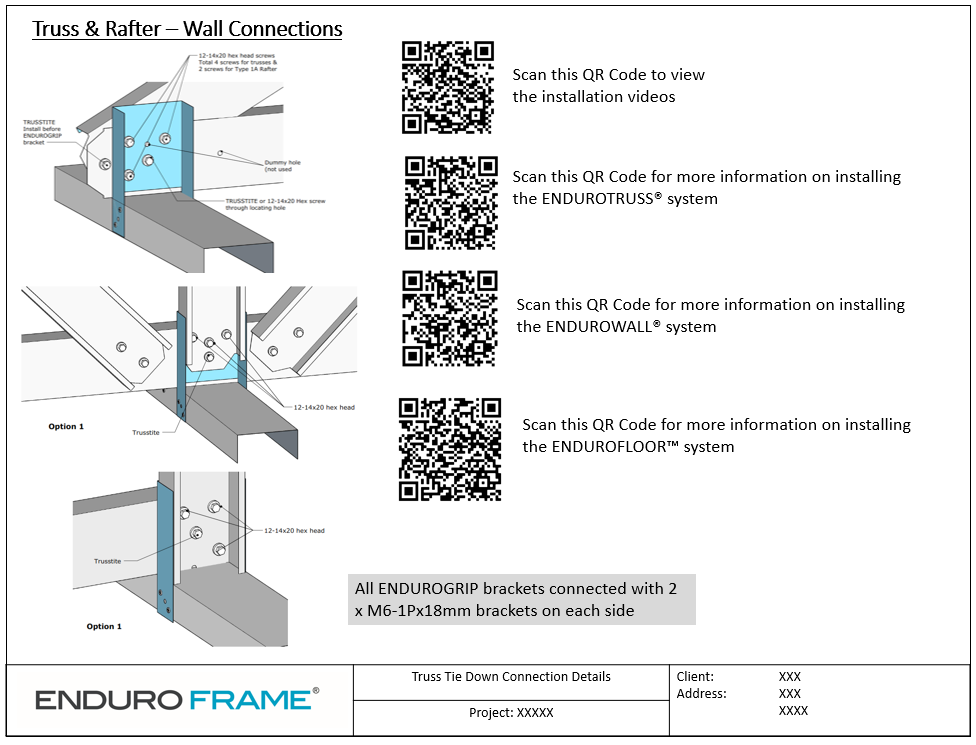
General Installation Details - 4 pages |
| Site |
| A3 / A4 |