...
Newer walls have a usage identifier rather than the full usage description and may have additional information such as the part length. It is still very easy to identify the usage using the following table:
| Identifier | Usage |
|---|---|
| TP | Top Plate |
| BP | Bottom Plate |
| HEAD | Header |
| SILL | Sill |
| STUD | Stud |
| NOGG | Nogging |
6.3 Assembly Procedure
ENDUROWALL® is generally factory assembled or assembly by a third party from completely knocked down (CKD) packs.
...
Lift and separate stud pack onto assembly table (this example has utilised Topspan® 40 sections on concrete block stacks as an assembly table).
Step
...
2 - Prepare bent tab studs
Identify and separate Endurotie® bent tab studs (90mm system only). The Endurotie® bent tab studs can be identified by the extension of the stud web section and double15mm hole punch for insertion of a frame anchor bolt (or similar).
- Place the stud with the web down.
- With a small cold chisel and a hammer, flatten the ribs on the rib in line with the stud flange.
- With a pair of duck bill pliers, bend the tab in the appropriate direction. (Refer to layout plan provided with job outputs.)
Step 3 - Lay out studs and insert into top and bottom plates
Layout all studs in sequential order, space out & orientate frame as per assembly sheet.
...
Step 10 - Install lintel flashing (where required)
Overlay and screw fix lintel flashing to top of frame as per assembly sheet and fixing details given in the Design Manual.
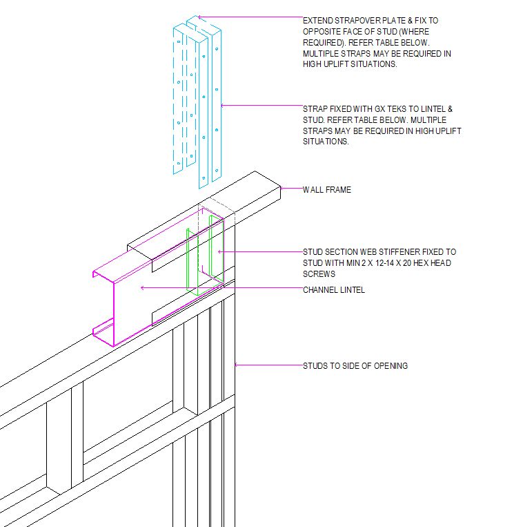
| Strap Size | Single or Double Sided | Straps | M6 Teks into Header and each Strap | M6 Teks into Jamb Stud and each strap |
|---|---|---|---|---|
| 30mm x 1.0mm | Single | 1 | 2 | 3 |
| 30mm x 1.0mm | Single | 2 | 2 | 3 |
| 50mm x 1.0mm | Single | 1 | 4 | 6 |
| 50mm x 1.0mm | Single | 2 | 4 | 6 |
| 30mm x 1.0mm | Double | 1 | 2 | 6 |
| 30mm x 1.0mm | Double | 2 | 2 | 6 |
FIGURE 6.17 - Beam Header Fixing Details
...


