ENDUROFLOOR Installation Manual
Table of Contents
Table of Figures
Overview
The ENDUROFLOOR™ system has been developed as an add-on intermediate floor system to be manufactured from an ENDURO® rollformer using standard ENDUROFRAME® components. It shall be able to be manufactured from both a 75 and 90mm section. A 75mm system shall be able to be made from gauges between 0.55 – 1.2mm thick, and the 90mm system shall be able to be manufactured from 0.55 to 1.2mm thick steel. Where possible, options shall remain open so the floor system can be manufactured on a Smartruss rollformer. Due to potentially being manufactured on Smartruss rollformers – and to increase the strength of the trusses – it will be used in its strong axis.
The ENDUROFLOOR™ system is designed to be used as part of the ENDUROFRAME® system but could also potentially be used as a standalone floor system to rest on wall frames, providing the loads are conforming with ENDUROFRAME® building system. Due to the variable and generally high corrosivity found in subfloor environments, TRUECORE® steel is not recommended for this application.
Scope of Manual
- This manual has been prepared for the construction of steel framed floors within the following parameters:
- Only ENDUROFLOOR™ components made from TRUECORE® steel and made with the ENDURO® rollformer can be used.
- Standard floor truss spacings are at 600mm or 450mm (max) centres dependent on floor truss design limitations. Other spacings may require additional engineering.
- Suitable for particle board sheeting and 75mm autoclaved lightweight concrete panels
Product performance
The ENDUROFLOOR™ system has been designed in accordance with relevant Australian Standards and the requirements of the Building Code of Australia.
The floor framing system will perform in accordance with ENDUROFLOOR™ design documentation if installed in accordance with the recommendations and details set down in this manual and related references. This manual contains vital information. Please read it carefully.
For more information and technical support, contact: www.enduroframe.com
Refer to www.truecore.com.au for locations where ENDUROFRAME® can be warranted.
General notes to be read before you use this manual.
- This Manual has been prepared for a range of floor framing designs using ENDUROFLOOR™ building components manufactured from TRUECORE® steel supplied by BlueScope Steel, its licensed manufacturers or dealers.
- The ENDUROFRAME® Building System has been designed as a complete framing system.
- All erection and connection details must be made in accordance with the relevant standard connection drawing details contained in this Manual or its supplements, or drawings output from the ENDUROCADD® software.
- Before commencement of any fabrication or construction develop a safety management plan to cover key risks. Key risks include, but are not limited to:-
- Working at heights
- Electrical safety
- Cuts and scratches
- Consider and install the appropriate level of safety equipment to manage identified risks. Safety equipment that may be required includes:-
- Personal protective equipment including safety glasses, gloves, hearing protection (when using power tools) and sunscreen;
- Appropriate fall protection equipment including guard rails, scaffolds, ladders, elevated platforms, safety mesh, and fall restraint harnesses
- A temporary earth should be established during the construction of steel frames and, upon completion, the steel house frames must be permanently earthed in accordance with the requirements of local electricity authorities.
- You should check with your local workplace health and safety authority to see what safety measures you need to put in place prior to and during construction. It is the responsibility of the installer/erector to ensure all local safe work practices are adhered to and the safety of the whole site is maintained at all times.
- For wiring in steel wall frames, nylon grommets shall be installed to run electrical cables through.
- Where insufficient detail is included in this manual for your project, seek specialist advice.
- Before you commence construction:
- You should check with your local government authority to see if any form of prior permission or approval is required;
- If you want to build or construct any attached structure, you should seek advice from a suitably qualified engineer to verify the capacity of your existing structure to withstand any additional load arising from the attached structure. You should also check with your local government authority to determine any specific requirements for the attachment to existing structures;
- You should check with your local workplace health and safety authority to see what safety measures you need to put in place prior to and during construction. It is the responsibility of the installer/erector to ensure all local safe work practices are adhered to and the safety of the whole site is maintained at all times.
- To ensure maximum lifespan of your house frame, consult your nearest ENDUROFRAME® fabricator for information regarding maintenance, handling, storage and any other technical assistance you may require.
Important disclaimer about this construction manual
Date of Issue
This Manual was issued on April, 2016. BlueScope Steel may make changes to this Manual in its sole discretion. You should check you are using the current version of the Manual before you start construction. Refer to www.enduroframe.com to check for the latest version.
Conditions of Use
If you use this Manual, you acknowledge and agree that your use is subject to the terms and conditions in this Manual. BlueScope Steel, its agents, officers, employees, subcontractors or consultants make no representations, either expressed or implied, as to the suitability of the information and data in this Manual for your particular purposes. It's your responsibility to ensure the design you use is appropriate for your needs, the products you have purchased, your site and structural limitations and your building and construction capabilities. It is recommended that you obtain qualified expert advice.
Use of Genuine Materials
Structures in this Manual should only be built or constructed using ENDUROFLOOR™ made from TRUECORE® steel and made with the ENDURO® rollformer or recommended third party products. Except as otherwise provided in these terms, any warranties only apply to you (if at all) if you use the genuine BlueScope Steel or recommended third party products and method of construction.
Check Delivery
It is important that you check all materials delivered to site against your invoice before you use them in your building or construction to ensure all components have arrived, are of the appropriate quality and are ready for installation.
Safety
Ensure that all barriers, scaffolding, and fall protection used in order to comply with safe work practices are installed so as not to damage or overload floor components.
Limitation of Liability
By using this Manual, you accept the risks and responsibility for all losses, damages, costs and other consequences resulting directly or indirectly from using this Manual. Except to the extent to which liability may not lawfully be excluded or limited, BlueScope Steel will not be under or incur any liability to any person for any direct or indirect loss or damage (including, without limitation, consequential loss or damage such as loss of profit or anticipated profit, loss of use, damage to goodwill and loss due to delay) however caused (including, without limitation, breach of contract, negligence, breach of statute and/or in equity), which may be suffered or incurred in connection with this Manual.
All rights reserved. No part of this brochure may be reproduced, stored in a retrieval system, or transmitted in any form or by any means, electronic, mechanical, recording or otherwise, without written permission of BlueScope Steel Limited. ABN 16 000 011 058
References
The following documents have been used in the development of this system:
- NASH Standard – Residential and Low-Rise Steel Framing Part 1: Design Criteria (2005)
- NASH Handbook – Design of residential & Low-rise Steel Framing (2009)
- NASH Technical Note 2 – Six Star Energy Efficiency Measures for Houses (March 2011)
- National Construction Code (Building Code of Australia - 2010), Australian Building Codes Board
- AS/NZS 1170.0: 2002 - Structural Design Actions - Part 0:General principles
- AS/NZS 1170.1: 2002 - Structural Design Actions - Part 1: Permanent, imposed and other actions principles
- AS/NZS 1170.2: 2011 - Structural Design Actions - Part 2: Wind actions
- AS4055:2012 - Wind loads for Housing
- AS/NZS 4600:2005 - Cold-formed steel structures
- AS 1684.2-2010 - Residential timber-framed construction – Non-cyclonic areas
- ABCB Protocol for Structural Software Draft Version 2011
- Minister's Specification SA A2.2 'Structural Engineering Software'
- NASH standard Residential and Low rise steel framing Part 1: Design Criteria 2005
- AS1860.2-2006 Particle Board Installation
Design
Components used in the ENDUROFLOOR™ system are specified by an ENDUROCADD® software Trained Software User referencing loads and span tables contained in the ENDUROFLOOR™ Design Manual. Any floors designed outside the scope of this Design Manual must be checked and signed off by a suitably qualified engineer. Any supporting beams, and connections required in the floor structure are to be specified by others.
Required on-site Tools and Equipment
When installing an ENDUROFLOOR™ Floor Framing System, the following tools and safety equipment may be required.
Power Tools
- screw gun
Tool Accessories
- 8mm (5/16”) hexagon socket
- extension bar (length up to 150mm)
- suitable metal cutting blades
- 8mm (5/16”) spanner or socket and handle
- No.2 and No.3 Phillips head driver bits (length up to 100mm)
Hand Tools
- double action tin snips (left, right and straight cut)
- spirit level
- chalk line
- step ladder
- vice grips
- measuring tape
Essential Safety Equipment
- eye protection (safety goggles)
- High visibility personal protective clothing
- hearing protection (when using power tools)
- protective gloves
- earth leakage circuit breaker for electrical equipment
- fall protection harness
- scaffolding, ladders, etc.
Material specification
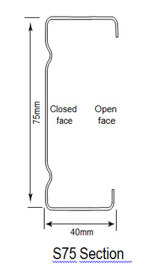
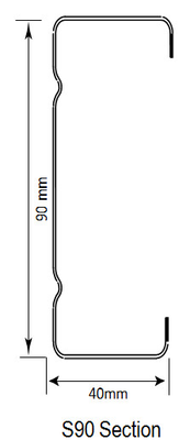
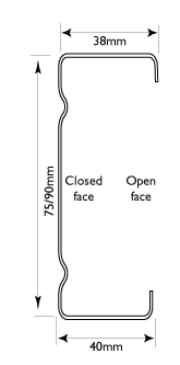
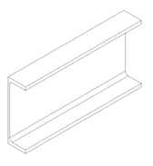
ENDUROFLOOR™ sections are roll-formed from TRUECORE® steel complying with AS1397:2011. The standard ENDUROFLOOR™ sections are shown in the graphic below. In the grade shown, the number prefixed with G indicates minimum yield stress in MPa; and the number prefixed with AZ or AM indicates minimum coating mass in g/m2.
- 0.55mm BMT, TRUECORE® G550 AM150 steel
- 0.75mm BMT, TRUECORE® G550 AM150 steel
- 1.00mm BMT, TRUECORE® G550 AM150 steel
- 1.20mm BMT, TRUECORE® G500 AM150 steel
ENDUROFRAME® sections
Components
A full list of components can be seen at this link - https://enduroframe.atlassian.net/wiki/x/L4Ms.
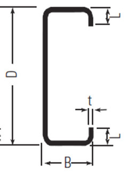
Rollformed Sections
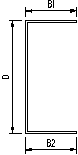
CEE section definition | Part No. | t | D | B1 | B2 | Lip | Feed Width mm | Section Type | Cee Sections |
|---|---|---|---|---|---|---|---|---|---|
mm | mm | mm | mm | mm | |||||
| C7575ra | 0.75 | 75 | 40 | 38 | 8 | 163 | Ribbed | ENDUROTRUSS® & ENDUROWALL® |
C7510ra | 1.00 | 75 | 40 | 38 | 8 | 163 | Ribbed | ||
C9075ra | 0.75 | 90 | 40 | 38 | 9 | 178 | Ribbed | ||
C9010ra | 1.00 | 90 | 40 | 38 | 9 | 178 | Ribbed | ||
C9012ra | 1.20 | 90 | 40 | 38 | 9 | 178 | Ribbed |
U section definition | Part Code | t | D | B1 | B2 | Feed width mm | Usage |
|---|---|---|---|---|---|---|---|
mm | mm | mm | mm | ||||
| U754475G550 | 0.75 | 78.5 | 43 | 45 | 163 | Dwarf plate |
U754410G550 | 1.00 | 78.5 | 43 | 45 | 163 | Dwarf plate | |
U904475G550 | 0.75 | 93.5 | 43 | 45 | 178 | Dwarf plate | |
U904410G550 | 1.00 | 93.5 | 43 | 45 | 178 | Dwarf plate | |
U904412G550 | 1.20 | 93.5 | 43 | 45 | 178 | Dwarf plate |
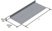
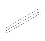
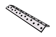
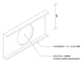
Lintels
Picture | Size | Application | Part No. |
|---|---|---|---|
| 200 x 35 x 1.5 | Single lintel used to resist roll-over of floor trusses at ends. |
Fasteners
IMPORTANT
Fasteners used in Structural applications must comply the ENDUROFRAME® Fastener Requirements specification which can be downloaded below.
Fastener Requirements - R2.pdf
Fasteners used should comply with the mechanical properties specified in the /wiki/spaces/EH/pages/35586106. Please check with the manufacturer of frames or the help portal to confirm fastener suitability.
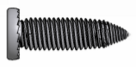
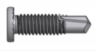
Picture | Description | Application |
|---|---|---|
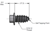 | 5/16-12 x 17 Hex Washer Trusstite | Primary connection of truss components through pre-punched holes. Both screws listed are suitable for the application. |
 | #10-16x16 hex head self drilling screw. | Low strength fixing- ceiling batten fix, chord and web boxing. |
 | Wall fastener – M6 x 1P x 15mm Smooth Top GX screw | Connecting wall frame components together through pre-punched holes. Used in ENDUROWALL™ FRAMING SYSTEM, |
| #12-14x20 hex head self drilling screws | General Framing Screw- Roof, Wall and Floor frame installation |
 | M6,0 x1P x 18,0 Smooth Top Gx Teks | Stiffening stud to plate connections and connecting lintels to plates |
 | M6.5 – 12 x 42 Hex Head Self Drilling Screw | Connecting smart rafters to truncated truss top chords. |
The use of the correct fasteners in the quantities shown in the truss fabrication drawings are essential to ensure the design capacity of the trusses are achieved.
The use of the correct fasteners in the quantities shown in the truss fabrication drawings are essential to ensure the design capacity of the trusses are achieved.
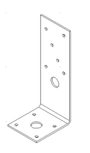
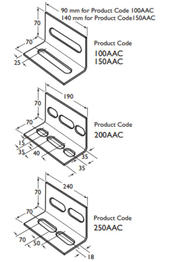
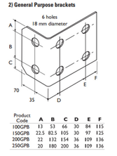
Brackets
Picture | Description | Application | Supplier | Part No. |
|---|---|---|---|---|
| CPAH Hold down bracket | Hold down bracket to connect joists to masonry walls | Pryda | CPAH |
Purlin cleats | Purlin cleats | Connecting purlins to purlins | Lysaght | |
| General purpose brackets | Connecting purlins to purlins | Lysaght | |
| ENDURO angle 45 x 45 x 1mm | Trimmer | ||
| Enduro Floor Truss Bracket 35 x 35 x 1mm | Connection and support of floor trusses to bearers/beams | ||
| SFS stiffening plate | Insert an oversized service penetration in a 300mm floor truss in its vertical axis. Length = 600mm | SFS |
Bracing & Blocking
Picture | Description | Application | Supplier | Part No. |
| Speedbrace | Rollover resistance brace | Pryda | SDB |
Strap bracing | Rollover resistance brace | Lysaght |
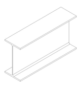
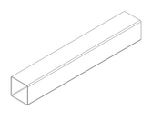
Beams & Bearers
Sections to be permitted for use in-plane, below floor truss or for cantilever applications.
Section Definition | Section Type | Part No. | t | D | B | L | Kg/m |
|
|---|---|---|---|---|---|---|---|---|
mm | mm | mm | mm | |||||
| Purlin | C10010 | 1.0 | 102 | 51 | 12.5 | 1.78 | Lysaght |
Purlin | C10012 | 1.2 | 102 | 51 | 12.5 | 2.10 | Lysaght | |
Purlin | C10015 | 1.5 | 102 | 51 | 13.5 | 2.62 | Lysaght | |
Purlin | C10019 | 1.9 | 102 | 51 | 14.5 | 3.29 | Lysaght | |
Purlin | C15012 | 1.2 | 152 | 64 | 14.5 | 2.89 | Lysaght | |
Purlin | C15015 | 1.5 | 152 | 64 | 15.5 | 3.59 | Lysaght | |
Purlin | C15019 | 1.9 | 152 | 64 | 16.5 | 4.51 | Lysaght | |
Purlin | C15024 | 2.4 | 152 | 64 | 18.5 | 5.70 | Lysaght | |
Purlin | C20015 | 1.5 | 203 | 76 | 15.5 | 4.49 | Lysaght | |
Purlin | C20019 | 1.9 | 203 | 76 | 19.0 | 5.74 | Lysaght | |
Purlin | C20024 | 2.4 | 203 | 76 | 21.0 | 7.24 | Lysaght | |
Purlin | C25019 | 1.9 | 254 | 76 | 18.5 | 6.50 | Lysaght | |
Purlin | C25024 | 2.4 | 254 | 76 | 20.5 | 8.16 | Lysaght | |
Purlin | C30024 | 2.4 | 300 | 96 | 27.5 | 10.09 | Lysaght | |
Purlin | C30030 | 3.0 | 300 | 96 | 31.5 | 12.76 | Lysaght | |
Purlin | C35030 | 3.0 | 350 | 125 | 30.0 | 15.23 | Lysaght | |
Purlin | SC40024 | 2.4 | 400 | 125 | 13.16 | Lysaght | ||
Purlin | SC40030 | 3.0 | 400 | 125 | 16.39 | Lysaght | ||
| PFC | 150 | * | 150 | 75 | N/A | 17.7 | |
PFC | 180 | * | 180 | 75 | N/A | 20.9 | ||
PFC | 200 | * | 200 | 75 | N/A | 22.9 | ||
PFC | 230 | * | 230 | 75 | N/A | 25.1 | ||
PFC | 250 | * | 250 | 90 | N/A | 35.5 | ||
PFC | 300 | * | 300 | 90 | N/A | 40.1 | ||
PFC | 380 | * | 380 | 100 | N/A | |||
| UB | 150UB14.0 | * | 150 | 75 | N/A | 14.0 | |
UB | 150UB18.0 | * | 155 | 75 | N/A | 18.0 | ||
UB | 180UB16.1 | * | 173 | 90 | N/A | 16.1 | ||
UB | 180UB18.1 | * | 175 | 90 | N/A | 18.1 | ||
UB | 180UB22.2 | * | 179 | 90 | N/A | 22.2 | ||
UB | 200UB18.2 | * | 198 | 99 | N/A | 18.2 | ||
UB | 200UB22.3 | * | 202 | 133 | N/A | 22.3 | ||
UB | 200UB25.4 | * | 203 | 133 | N/A | 25.4 | ||
UB | 200UB29.8 | * | 207 | 134 | N/A | 29.8 | ||
UB | 250UB25.7 | * | 248 | 124 | N/A | 25.7 | ||
UB | 250UB31.4 | * | 252 | 146 | N/A | 31.4 | ||
UB | 250UB37.3 | * | 256 | 146 | N/A | 37.3 | ||
UB | 310UB32.0 | * | 298 | 149 | N/A | 32.0 | ||
UB | 310UB40.4 | * | 304 | 165 | N/A | 40.4 | ||
UB | 310UB46.2 | * | 307 | 166 | N/A | 46.2 | ||
| RHS | 150 X 50 | 2 | 150 | 50 | N/A | 6.07 | |
2.5 | 150 | 50 | N/A | 7.53 | ||||
3 | 150 | 50 | N/A | 8.96 | ||||
4 | 150 | 50 | N/A | 11.6 | ||||
5 | 150 | 50 | N/A | 14.2 | ||||
6 | 150 | 50 | N/A | 16.7 | ||||
RHS | 125 X 75 | 2 | 125 | 75 | N/A | 6.07 | ||
2.5 | 125 | 75 | N/A | 7.53 | ||||
3 | 125 | 75 | N/A | 8.96 | ||||
4 | 125 | 75 | N/A | 11.6 | ||||
5 | 125 | 75 | N/A | 14.2 | ||||
6 | 125 | 75 | N/A | 16.7 | ||||
RHS | 100 X 50 | 1.6 | 100 | 50 | N/A | 3.64 | ||
2 | 100 | 50 | N/A | 4.50 | ||||
2.5 | 100 | 50 | N/A | 5.56 | ||||
3 | 100 | 50 | N/A | 6.60 | ||||
3.5 | 100 | 50 | N/A | 7.53 | ||||
4 | 100 | 50 | N/A | 8.49 | ||||
5 | 100 | 50 | N/A | 10.3 | ||||
6 | 100 | 50 | N/A | 12.0 | ||||
RHS | 75 X 50 | 1.6 | 75 | 50 | N/A | 3.01 | ||
2 | 75 | 50 | N/A | 3.72 | ||||
2.5 | 75 | 50 | N/A | 4.58 | ||||
3 | 75 | 50 | N/A | 5.42 | ||||
4 | 75 | 50 | N/A | 6.92 | ||||
5 | 75 | 50 | N/A | 8.35 | ||||
6 | 75 | 50 | N/A | 9.67 | ||||
| SHS | 100 X 100 | 2.5 | 100 | 100 | N/A | 7.53 | |
3 | 100 | 100 | N/A | 8.96 | ||||
4 | 100 | 100 | N/A | 11.6 | ||||
5 | 100 | 100 | N/A | 14.2 | ||||
SHS | 90 X 90 | 2 | 90 | 90 | N/A | 5.45 | ||
2.5 | 90 | 90 | N/A | 6.74 | ||||
3.5 | 90 | 90 | N/A | |||||
SHS | 75 X 75 | 2 | 75 | 75 | N/A | 4.5 | ||
2.5 | 75 | 75 | N/A | 5.56 | ||||
3 | 75 | 75 | N/A | 6.60 | ||||
3.5 | 75 | 75 | N/A | 7.53 | ||||
4 | 75 | 75 | N/A | 8.49 | ||||
5 | 75 | 75 | N/A | 10.3 | ||||
6 | 75 | 75 | N/A | 12.0 | ||||
| Boxspan | 100 x 50-12 | 0.6 | 100 | 50 | N/A | 2.05 | Spantec |
Boxspan | 100 x 50-16 | 0.8 | 100 | 50 | N/A | 2.71 | Spantec | |
Boxspan | 150 x 50-12 | 0.6 | 150 | 50 | N/A | 2.51 | Spantec | |
Boxspan | 150 x 50-16 | 0.8 | 150 | 50 | N/A | 3.33 | Spantec | |
Boxspan | 150 x 50-20 | 1. 0 | 150 | 50 | N/A | 4.14 | Spantec | |
Boxspan | 200 x 50-16 | 0.8 | 200 | 50 | N/A | 3.94 | Spantec | |
Boxspan | 200 x 50-20 | 1.0 | 200 | 50 | N/A | 4.91 | Spantec | |
Boxspan | 250 x 50-20 | 1.0 | 250 | 50 | N/A | 5.68 | Spantec | |
| SFS Rollformed Joist | 1.5, 1.9 & 2.4mm | 300 | 50 | N/A | SFS |

Truss Connections
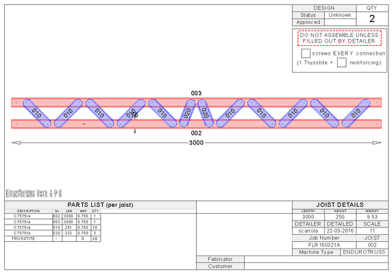
Chord to chord connections do not have any name, and are treated the same as webs. The only information that is recorded in the connection are the number of fasteners, and these shall be the same for connection at each end of the chord or web.
The only other type of connection is a step down connection which will be referred to as SD-6 which indicates the number of self tapping fasteners connecting the top chord with the step down chord.
The number of screws indicated is the combined number of Trusstite and reinforcing screws.
When assembling trusses adopt the following rules for screw placement:-
- Screws should be placed a minimum of 18mm centre to centre
- Screws should be placed a minimum of 10mm from the end of a component
- Screws should be placed a minimum of 8mm from the edge of a component
Screws should be placed where shown on the connection drawings within the above spacing constraints
Note
Connections external to the truss (e.g. Bridge truss to Girder Truss, Rafter to truss, truss to support) are covered in the relevant block assembly sections of this manual.
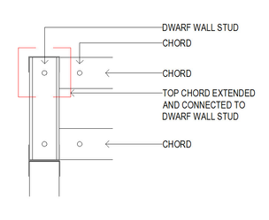
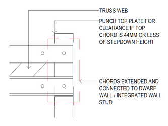
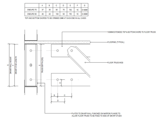
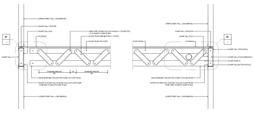
All floor joists require a vertical end member. This may be a stud continuing into the floor joist from the level below in an integrated wall, a dwarf stud in an independent wall or an additional vertical chord added where there neither the integrated wall nor independent wall are selected or where the joist connections to a beam.
| Connection between extended top chord of floor truss and dwarf wall stud. |
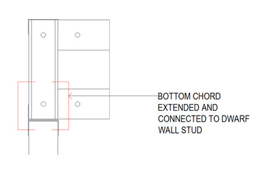
| Connection between extended bottom chord of floor truss and dwarf wall stud. |
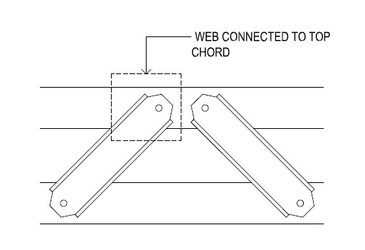
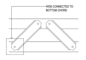
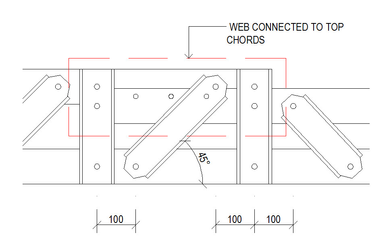
| Connection between web and top horizontal chord of floor truss. |
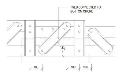
| Connection between web and bottom horizontal chord of floor truss. |
| Compound connection for use in set downs such as bathroom wet areas and balconies. This connection compliments the bottom chord connection (below) |
| Compound connection for use in set downs such as bathroom wet areas and balconies. This connection compliments the top chord connection (above) |
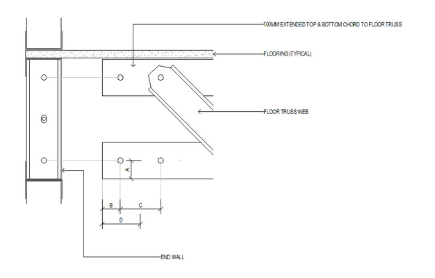
| Connection between floor joist step down and end wall. |
Notes on Vibration
Floor vibration from general footfall traffic is subjective to each end user. Some people prefer a tight (high frequency) floor whilst others prefer a floor with more resilience (bounce). Each floor design is affected by multiple circumstances including joist span and spacing, flooring type and thickness, furniture supported, loads imposed from roof and supporting walls and supported partition (non-loadbearing) walls.
The ENDUROFLOOR™ system defined in this manual has been tested to have a minimum harmonic frequency of 8 Hz with joists at a maximum span and centres indicated in the attached span tables, and sheathed with either 22mm or 19mm particleboard flooring fixed in accordance to AS1860. This value is considered to be acceptable in most circumstances.
Where a higher frequency (tighter) floor is required, reduced spans, the use of stiffer/thicker flooring or an extra layer of flooring may be utilised with varied results.
Truss Assemblies
General
For ENDUROTRUSS® pre-punched holes are formed in chords and webs during rollforming. The perimeter chords are connected using TRUSSTITE® fasteners at changes in direction. The primary shape is formed by aligning pre-punched holes in the adjacent chord members and inserting a TRUSSTITE® screw to form a connection. Additional screws, stiffeners or brackets may be required to form the connection. Webs join the chords of a truss forming triangular patterns transmitting tension or compression stresses. The web to chord connections are formed by aligning the pre-punched holes in the end of the webs with pre-punched holes along the chord members and inserting a TRUSSTITE® fastener. Additional self drilling screws may be required to add strength to the connection. The full geometry of the truss is set by the connection of the pre-punched and notched components. ENDUROTRUSS® Channels have one flange wider than the other enabling the boxing of the section forming a tubular section with high torsional strength. To facilitate the boxing of chords after assembly the narrow flange must be placed on the external perimeter of the truss and on the top of horizontal rails within the truss.
Flush Truss
Flush truss is not an option with the ENDUROFLOOR™ truss system.
Pre Camber
There will be no pre-camber in the floors design or manufacture.
Manufacturing Crib Allowance
Crib lengths are necessary for trusses to fit in between walls and beams. The standard crib length is 2mm from each end of a truss but can be adjusted as necessary by the Trained Software User in the ENDUROCADD software. The following crib lengths shall be assumed:
- Beam lengths - User defined
- Length of trusses between 2 walls - 4mm or user defined
- Length of trusses between 2 beams - 10mm or user defined
- Length of trusses between a beam and a wall 5mm or user defined
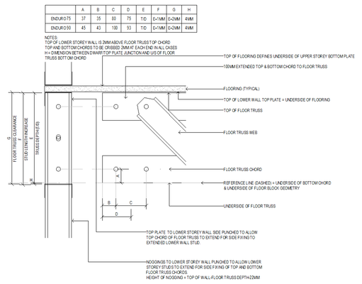
Floor truss component cribbing for Independent wall systems
Floor truss component cribbing for Integrated wall systems
Standard Floor Truss
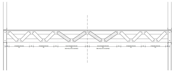
A standard floor truss has the top and bottom chord running parallel (vertical end chords may be used where specified). The end of a standard floor truss may either sit on top of a load bearing wall or bearer, fit into an integrated wall or butt up against a beam. Vertical webs are placed directly above, below or between load bearing walls and supporting beams. Common webs will be placed at 45 degrees from the end of the floor truss starting at the top chord, and any non-standard webs are in the middle of the truss span. This may mean that 2 webs in the centre of the truss are non-standard lengths and can vary between 35 degrees to 90 degrees (vertical).
In order to simplify manufacturing and assembly of trusses, standard lengths are used for webs and vertical chords (where specified). This will enable standard parts to be pre-made and stored, and will make it easier to find parts during assembly. Only non-standard length parts will therefore need to be defined on assembly sheets which will greatly de-clutter drawings given these trusses will be quite dense. Location of standard webs shall be placed from the outside (support locations) working inward toward the middle of the span. In the majority of cases, this would only require a maximum of 2 webs to be individual.
Vertical end members are always required on floor trusses. These may be studs extended from the wall below, or as part of an independent wall. If alternatives are selected which are not in an integrated or independent wall the vertical end chords need to be added.
Detail: Typical standard floor truss - all webs at 45 degrees
Detail: Typical standard floor truss - middle webs at minimum 35 degrees
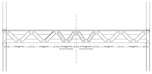
Detail: Typical standard floor truss - middle webs greater than 45 degrees
Design Options
The following options for standard floor trusses include:-
- Top chord section (where specified, the 2 vertical chords at the end of the truss shall be the same section)
- Single or boxed top chord section
- Bottom chord section.
- Single or boxed bottom chord section
- Web section. This also applies to any vertical sections above a load bearing wall.
- Truss depth (this shall be from 250mm, 300mm, 350mm, 400mm and 450mm)
All chords have square end cuts. All floor trusses have the webs back-to-back with the chords. The configurations for standard floor trusses are shown below.
Detail: Typical standard floor truss - Context and components
The end connection detail of a standard floor truss is shown in the figure above. The standard truss fits into and connects with Trusstite screws to the end wall which is manufactured separately to the standard floor truss. With the Integrated wall type the floor truss is not supported by the nogging.
Detail: End connection punch locations
Connecting Floors from Upper Wall to Lower Wall
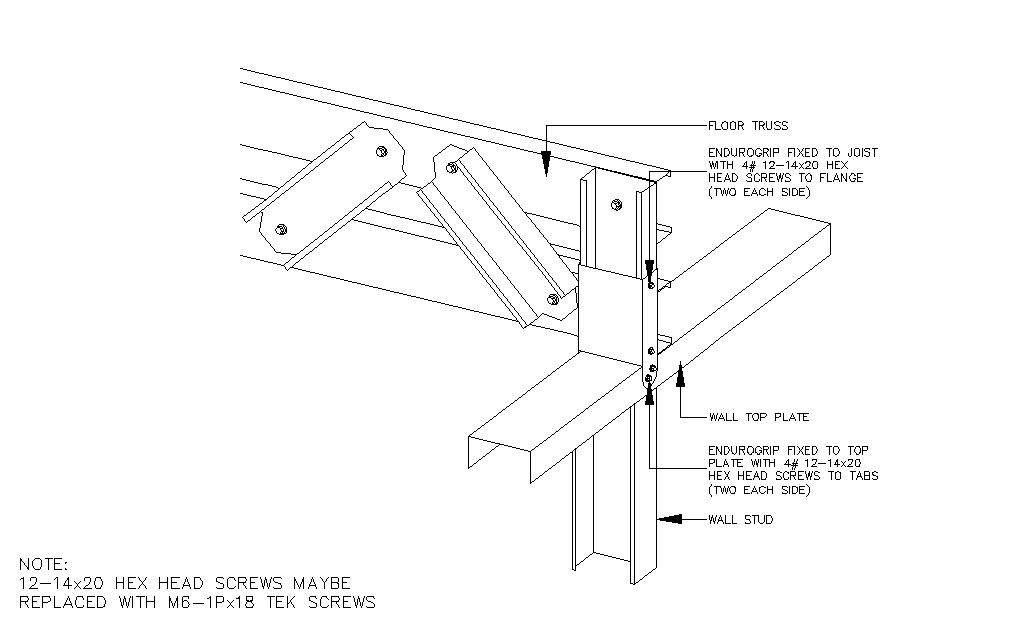
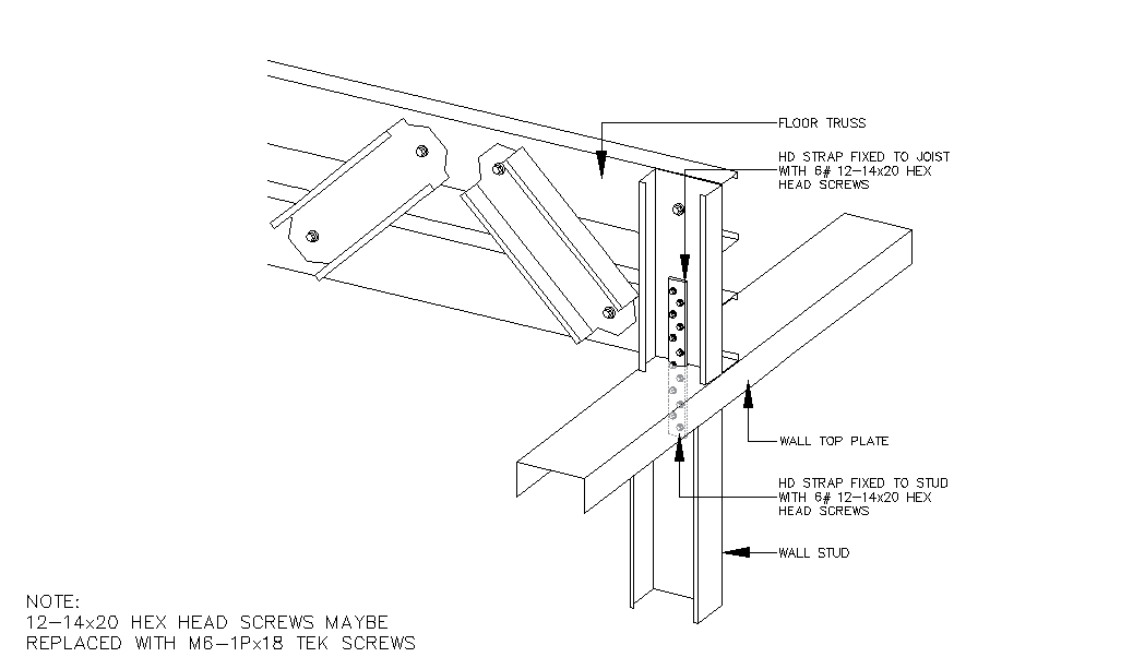
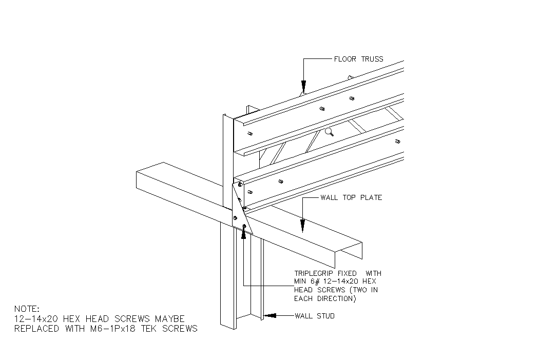
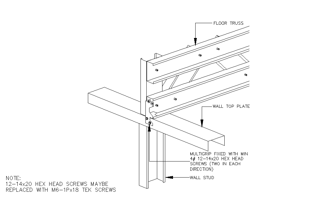
The following options are available to connect upper storey walls to lower storey walls is shown in the table below. This assumes that the plates used in both the upper and lower walls are minimum 0.75mm BMT.
REF | Connection Description | Upper Wall | Lower Wall | Capacity kN | ||||
|---|---|---|---|---|---|---|---|---|
| Ind | Int | None | Ind | Int | None | |||
| A | 32 x 1.0 mm strap fixed with min 2 x 12-14x20mm screws to each end | Y | Y | Y | Y | NA | Y | 6.2kN |
| B | Enduro-Grip fixed with min 8 x 12-14x20mm screws to flange and tabs | N | N | N | N | NA | Y | Unstiffened top plate 0.75mm - 3.37kN Stiffened top plate 0.75mm - 8.35kN Unstiffened top plate 1.0mm - 6.12kN Stiffened top plate 1.0mm - 14.34kN |
| C | 200 x 25 x 3mm HD strap tie-down fixed with min 6 x 12-14x20mm screws | Y | Y | Y | Y | NA | Y | 23.65kN |
| D | Pryda Trip-L-Grip fixed with min 6 x 12-14x20mm screws (2 in each direction) | N | N | N | N | NA | Y | Plate thickness 0.75mm - 4.9kN Plate thickness 1.0mm - 6.0kN |
| E | Pryda Multi-Grip fixed with min 4 x 12-14x20mm screws (2 in each direction) | N | N | N | N | NA | Y | Plate thickness 0.75mm - 3.75kN Plate thickness 1.0mm - 4.4kN |
#. Direct upper stud to floor truss alignment required. No continuous lintel on top of floor truss..
*. Continuous lintel on top of floor trusses required
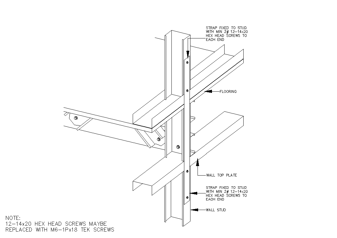
A - 32 x 1.0 mm strap fixed with min 2 x 12-14x20mm screws to each end
B - Enduro-Grip fixed with min 8 x 12-14x20mm screws to flange and tabs
C - 200 x 25 x 3mm HD strap tie-down fixed with min 6 x 12-14x20mm screws
D - Pryda Trip-L-Grip fixed with min 6 x 12-14x20mm screws (2 in each direction)
E - Pryda Multi-Grip fixed with min 4 x 12-14x20mm screws (2 in each direction)
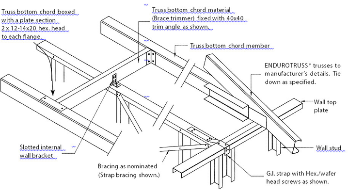
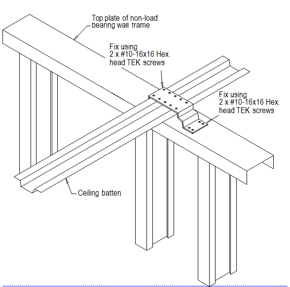
Connecting non-load bearing internal bracing wall on upper level to floor
When the upper wall is a non-load bearing bracing wall which lands on a support floor truss and the bracing force needs to be transferred to the floor joists, refer to connection table below for selection of connection capacity.
Where the wall is in between the floor joists, floor trimmers are to be used to support bracing walls when:
- Wall parallel to floor truss and does not land directly on a floor truss
Wall perpendicular/diagonal to floor truss and ends of bracing panel do not land on floor truss
Note
Bracing panel is the portion of a wall frame where cross bracing is used. End of bracing panel usually is located at the intersection between cross bracing and wall bottom plate.
Note for load bearing walls
This does not cover load bearing walls which should be supported by a joist or a beam directly under the load bearing wall. Refer to the Section 3.2 for informaiton on tie downs between load bearing upper walls and lower walls, and connection capacities in Section 3.3. The design of supporting structure under load bearing walls should be referred to a suitably qualified engineer.
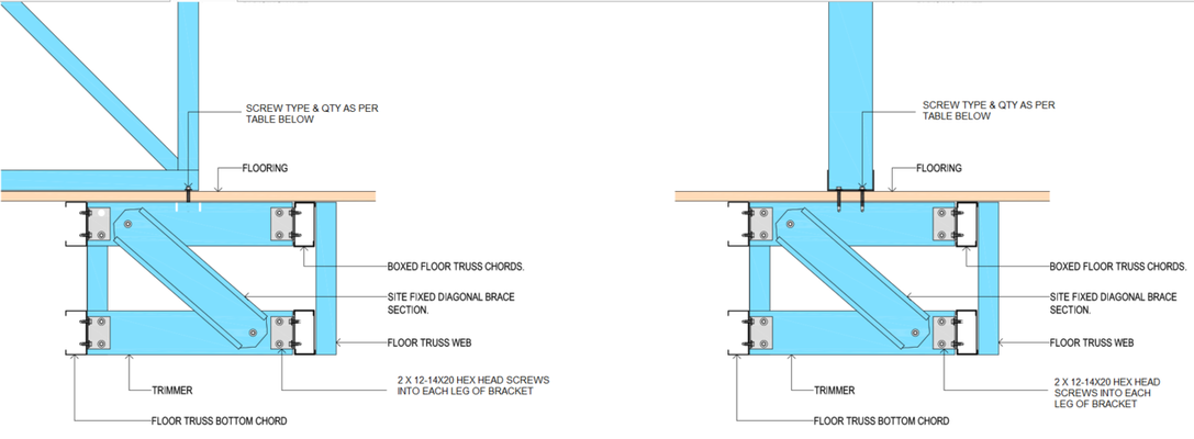
Trimmer construction
Floor truss trimmer consist of top, diagonal and bottom members. The trimmers should have the same size and BMT as the floor truss chord. The top trimmer is position at the same level as the floor truss top chord. The bottom trimmer is position at the same level as the floor truss bottom chord. A brace member of the same size and gauge as the trimmers should be fixed to the back of the top and bottom trimmers diagonally using 2x 12-14x20 metal teks per connection. Trimmer connection bracket must be minimum 45x45x1.0mm angle. Trimmer must be fixed to bracket with 2x 12-14x20 metal teks into each leg at each end.
Where ever the trimmers clash with floor truss web members, adjust the location of trimmers away from the web junctions to allow for practical installation.
To connect the trimmer to the open side of the top/bottom chord, use either method from below:
- Use an angle bracket with enough leg distance e.g. 100mm when fixed from the inside of the chord.
- Box the chord at the trimmer location using a 200mm chord section with 2 x M6 Tek screws on both the top and bottom flange at each end, and connect the trimmer to the boxed chord using an angle bracket.
Trimmer locations
For bracing walls, trimmers are positioned at the end of bracing panels, for a single wall with 2 or more bracing panels, trimmers are required at the ends of each bracing panel.
Bracing wall bottom plate to trimmer / floor truss top chord uplift and shear capacity
Floor joist top chord / trimmer BMT (mm) | Connection capacities (kN) | |||||
|---|---|---|---|---|---|---|
No. of fastener x fastener size | ||||||
4x 12-14x20 | 6x 12-14x20 | 6x 14g-10 | ||||
Uplift | Shear | Uplift | Shear | Uplift | Shear | |
0.75 | 3.6 | 12.3 | 5.3 | 18.4 | 7.2 | 21.0 |
1 | 5 | 16.3 | 7.5 | 24.5 | 11.3 | 28.1 |
1.2 | 7.9 | 18.5 | 11.8 | 27.8 | 12.4 | 31.8 |
Intermiedate fixing along bottom plate of bracing panels to floor joist | 12g-14 hex head metal teks at 450/600mm standard spacing between studs | |||||
Uplift capacities are based on NASH Standard Part 2, Shear capacities are based on AS4600 hole bearing calculation.
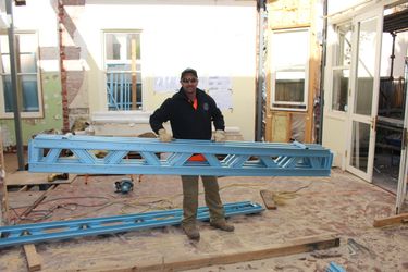
Handling of Endurofloor trusses
Trusses must be fully supported in either horizontal or vertical planes when being transported. Care must be taken when tying down and lifting trusses not to put an excessive pressure on chords, webs or joints. An additional 12-14x20 hex head tek screw may be inserted between the Trusstite screw and the flange closest to the inside of the truss to provide additional structural stiffness and ease of transportation.
Most floor trusses may be lifted by hand, however where cranage is required, use slings. Slings should be located at equal distances from truss centrelines, and be approximately one-third to one-half the truss length apart.
The angle between the sling legs should be 60 degrees or less and where truss spans are greater than 9000 mm, a spreader bar with suitable attachments at the web-chord connection should be used.
Note
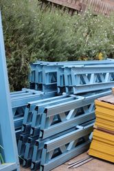
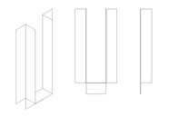
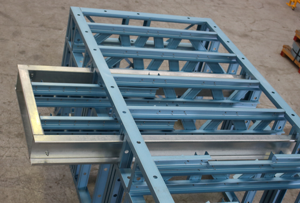
Floor trusses exposure and storage
Where trusses are stored on site, they should be blocked above firm ground so that they do not come into contact with the soil and to protect them from ground water:
- If the trusses are stored on their side, the blocking should be at 2.0m to 2.5m centres or as required at joints, to prevent bending of the trusses. Avoid using copper, chemically treated timber or EPDM based materials as blocking.
- If the trusses are stored vertically as shown in image above, they should be supported at the designed support locations or bottom chord panel points, and in a manner that will be prevented from tipping or toppling.
- The truss chords should be sloped such that water drains off.
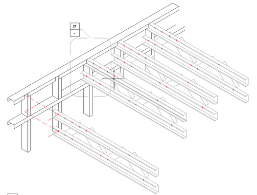
Truss identification
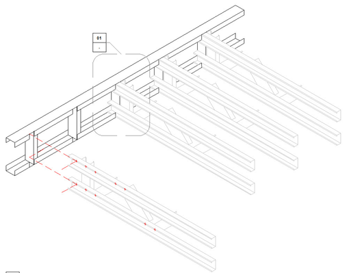
A summary of the description of floor trusses is shown in the Typical Floor Detail below. Wall have been removed in the attached image for clarity.

Detail: Typical floor
Standard Floor truss
A standard floor truss consists of parallel top and bottom chords that may be boxed (if necessary), and common webs.
Detail: Standard floor truss
Stepdown Truss
A stepdown truss is used where a reduced top level is required in a wet area such as a bathroom or laundry. Due consideration should be given for the possibility of increased floor dead loads from reinforced mortar bed tiling. Stepdown trusses can also be used on external deck areas or as an architectural feature in alternate floor levels.
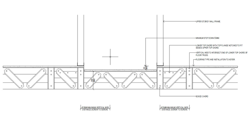
Detail: Stepdown truss
Cantilever Floor Truss
A cantilevered floor truss is used where the span of the truss is required to be extended beyond the supporting wall (or beam) below. Where the floors are cantilevered beyond their capacity, an additional beam may be required to support the ends of the floor trusses. The beam at the end of the floor truss should in turn be supported by beams with sufficient back span. These beams should be designed by a certified engineer. A cantilever floor may also incorporate a stepdown to facilitate a difference in level for rainwater drainage. This step down should not exceed 50mm below the level of the main floor..
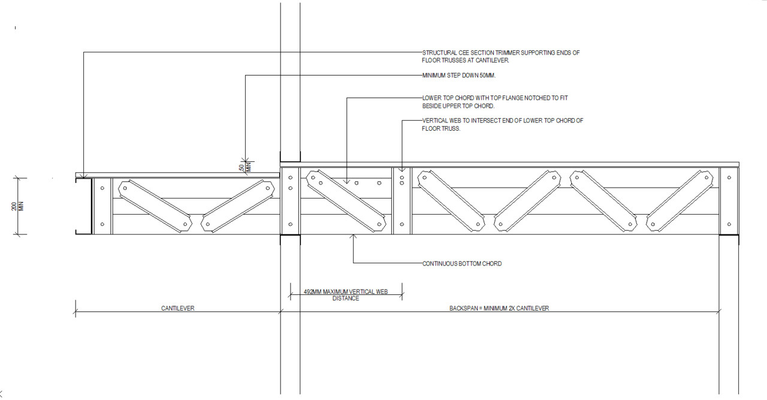
Detail: Cantilever area truss
Detail: Example of cantilever truss end supported by beams which back span across floor
Truss Assembly
ENDUROFLOOR™ Floor Framing System marking and branding
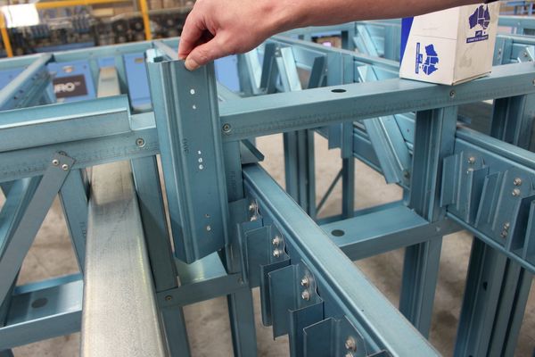
All ENDUROFLOOR™ Floor Framing System parts are coded with information to assist erectors in the assembly process. This matches the part information shown on the assembly drawings.
All ENDUROFLOOR™ Floor Framing System chords, where they are long enough, are coded with the following:
- Part Number, Floor Truss Number, Job Name/Number, Part Length, and Part Usage.
- They also contain the rollformer number and date of manufacture for traceability purposes.
ENDUROFLOOR™ webs are marked with the truss number and the part number.
With this information, installers can identify what the part is and where it is intended to be used in the structure. The illustration below shows how the coding works:
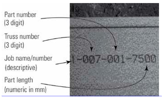
The example above illustrates that this member is for Job Number 1, it is part of floor truss number 7 (as numbered by the software in the construction drawings), it is part number 1 and is 7500mm in length.
Chord to chord connection identification
The connection information is displayed at the top right of the ENDUROCADD® software generated fabrication sheet showing all the connections used in the specific floor truss. Unless specified, this number applies to all connections on the floor truss. All chords must be assembled with at least a single Trusstite and a single 12-14x20 hex head reinforcement fastener.

Standard Truss Assembly
Step 1 - Part Identification
Unpack the trusses and sort into truss lots using the branding as a guide. Identify the chords and webs from the branding information on the parts. To simplify the assembly process, common webs with a predetermined length are used in the majority of the floor trusses with individual webs allowing for manufacture of different floor truss lengths. Refer to ENDUROTRUSS® Framing System marking and branding for more information on how to identify parts.
Step 2 - Truss Layout & Chord Assembly
Identify the chords and lay toes down on a level surface or assembly table and align as per assembly drawing. Vertical chords will lay back-to-back with horizontal chords. Pre-punched holes are provided for locating truss screw to connect the chords together. All sections for chords have square cut ends.
Note
Branding is on the side flange which will be on the outside of the truss chords which can aid in assembly and laying out.
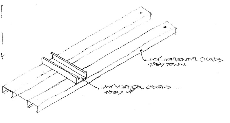
Detail: Initial chord placement
Step 3 - Align holes and install a locating truss screw
When carrying out the primary assembly of the end webs and chords, align holes as shown and install a locating Trusstite screw in holes.
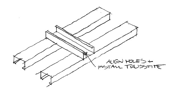
Detail: Hole alignment and trusstite installation
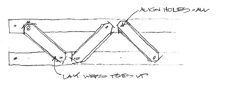
Step 4 - Web Installation
If they are linked together, separate linked webs by cutting or snapping pieces apart. If webs are joined they will be attached in the order required for assembly (Left to right). Snip or snap the webs apart and position each one over the truss chords near their final location. As this is only a non-flush truss the branding on the webs will face towards the top of the truss and toes of the channel will face up and no notches are provided at the web ends.

Detail: Web separation
Step 5 - Align holes and fix connection with a locating truss screw
Using part identifier numbers layout the webs in accordance with the Assembly Sheet. Line up the 6mm locating holes on the ends of the webs with the appropriate holes on the floor truss chords. Install a locating Trusstite® screw into the aligned holes ensuring that the screw is driven firmly home and does not strip.
Should the locating truss screw strip, reduce the driver torque and place a 12-14x20mm self drilling screw 20mm minimum from the locating truss screw.
Detail: Web placement
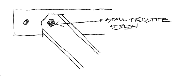
Detail: Web fixing
Step 6 - Check floor truss dimensions and alignment
Before inserting any reinforcing screws check the overall dimensions of the floor truss against the Assembly Sheet. For a complex shape truss, lay it on top of a previously assembled one and check they are the same.
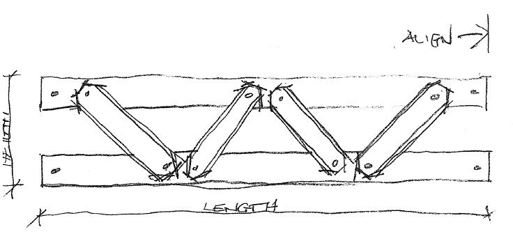
Detail: Check measure
Step 7 - Reinforcement screw installation
Once aligned, install 12-14x20mm hex head screws between the Trusstite fastener and the inside flange of the chord as shown in the detail below.
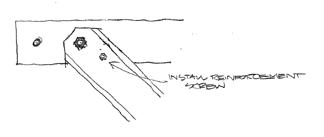
Detail: Reinforcement screw installation
ENDUROFLOOR™ Floor Framing System stiffening and reinforcement
Refer to the ENDUROCADD® software generated connection drawing and the assembly drawings to identify reinforcing screws required to complete truss assembly. Primary fixing screws are self-locating Trusstite® screws fastened through pre-punched holes, while reinforcing screws are #12-14 x 20mm hex-head self-drilling fasteners, without washers. Stiffening screws should be installed a minimum of 17mm from each other and the locating screw and a minimum distance of 10mm from the edge and 17mm from the end.
From the appropriate connection drawing, identify the location and the screws required. Install as shown on the drawing.
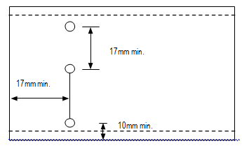
Detail: Screw distances
Web connection stiffening
Identify webs requiring reinforcing screws by referring to the span tables. For example, all web to chord connections require 2 screws which consists of 1 x Trusstite® and 1 x 12/14 x 20mm Hex Head reinforcing screw. This is indicated in the span tables below in white background text. Where grey background is behind the text in the table below, 3 screws are required consisting of 1 x Trusstite® and 2 x 12/14 x 20mm Hex Head reinforcing screw.
Chord Boxing
Where called for in the Assembly Sheet, chords are to be boxed using supplied boxing channel. Boxing is to be fixed to the inside flanges of chords using either 10-16 x 16mm wafer head self drilling screws, or M6,0 x1P x 18,0 Smooth Top Gx Teks self drilling screws as per the diagram below. These are fixed 50mm from each end of the boxing and at 600 mm nominal centres along the boxing. The top flange of the top chord will restrained by screws fixing the flooring fixings, and the bottom flanges of the bottom chords are restrained by the ceiling batten fixings.
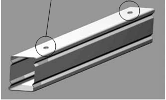
Chord Boxing Detail
Points for construction
Floor trusses must be installed plumb and straight
While installing the floor, trusses must be fixed plumb and straight. After fixing, if a bow or tilt is evident, the trusses have not been installed correctly. In this case, the problem must be rectified before proceeding further.
Warning
Correct direction of ENDUROFLOOR™ chord profile
The direction of the channel section used for the chord should be as depicted on Truss Assembly diagrams in the Detail: Typical standard floor truss assembly sheet.
Trusses should be oriented as shown on the truss layout drawing provided and ensure load bearing points shown on the assembly drawings align with load bearing walls. Truss chords are inkjet marked to indicate Top Chords - 'TC' - and Bottom Chords - 'BC'. Ensure that trusses are installed in the correct orientation.
Detail: Typical standard floor truss assembly sheet
Straightness
Trusses must be installed with an overall out of plane straightness not greater than L/500 where L is the length of the member as shown in the Detail below.
Differential in vertical bows between adjacent members must not exceed 1/150 of their spacing or 6mm whichever is less.
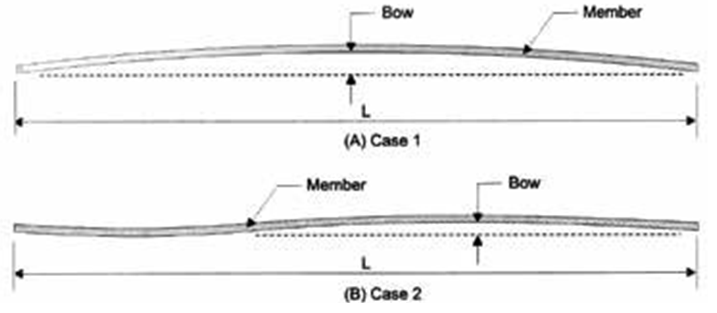
Detail: Straightness
Plumb
Out of plumb at any point along the length of the truss from top to bottom must not exceed the minimum of h/100 or 20mm.
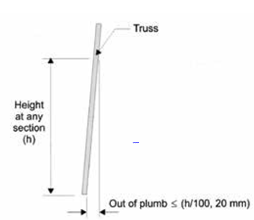
Detail: Plumb
Floor Construction
General and design
The trusses are designed by the ENDUROCADD® design software to suit the specific floor geometry and loads applicable to the site conditions. Additional loading such as spa baths, billiard tables, heavy fixed cabinetry etc. require special consideration at the time of design and the placing of these additional loads must be referred back to the designer.
Prior to construction
Before commencing floor construction:
- Check the support structure in particular the plan dimensions, the plumb and level of the support structure, the straightness of the supporting walls or beams and that the structure is adequately braced, stable and tied down. Rectify support structure if found deficient prior to proceeding.
- Floor trusses must be inspected and any damaged parts must be reported immediately to the manufacturer to ensure correct rectification. Approval for on site rectification must be obtained from the truss manufacturer prior to installation.
- Check that the ENDUROCADD® software generated truss layout matches the building and that all truss set-out dimensions and truss identification marks have been provided.
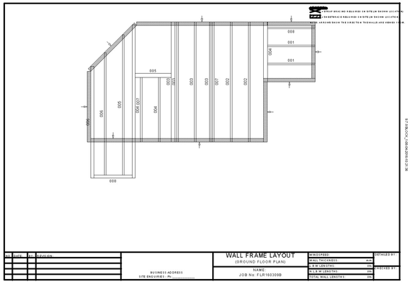
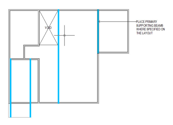
Prior to lifting any floor trusses into place, mark out the support beam and floor truss locations on the top wall plate, using the supplied Floor Truss Framing Layout as a reference.
It is generally best practice to install support beams before proceeding with the installation of standard floor truss runs.
Whilst installing floor trusses ensure that each floor truss is placed in the correct position, correctly orientated and plumb (using a spirit level).
If trusses are fixed to the support structure using brackets these are often installed in the marked positions prior to positioning the trusses.
The floor trusses may be aligned to load bearing studs. In cases where it is not aligned, sufficient capacity shall be provided for top plate using lintels or stiffeners.
Check that design floor truss spacings have not been exceeded.
- Check that ends of trusses are restrained either by a stud or a vertical end chord
NOTE:
Truss orientation and Position
The layout drawings specifies the correct floor truss positions. With integrated and independent walls the position of chords will be set by pre-punched holes and sections running around the perimeter of the floor..
The front of the floor truss is the flat (unlipped) face of the floor truss horizontal chords. Looking at the floor truss from this direction identifies the Left and Right hand floor truss ends. Ensure floor trusses are orientated as shown on the floor truss layout, and with chord marked with TC at the top of the truss and BC at the bottom of the truss.
Floor Truss Numbering
During the detailing / fabrication process the floor trusses are numbered to accurately identify them. These numbers are shown on the floor truss layout and form part of the floor truss branding. Floor trusses may have identical shape but may differ in the material used or number of screws in the connections. Ensure that the correct floor truss is used in its specified location in the floor.
Internal load bearing points
Where floor trusses are supported by internal walls, the floor truss web configuration will be designed to satisfy the load concentration at the load bearing point. Ensure that the floor truss is installed such that bottom chord to web connections are within 5mm to the support points. The builder should ensure that these loads are accommodated in the footing design.
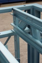
Connecting Joists to Beams
There are several methods which may be used to connect joists to floor beams. Please note that beams may need to be packed to either reach the floor level or to provide a fixing point for the joists. Some methods for packing beams are shown below.
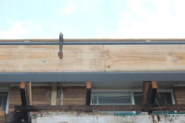

Picture: Packing beams
Install connection brackets to primary support beams for all secondary support trimming beams and floor trusses (Note: connection to be specified by suitably qualified engineer or manufacturer). Examples of joist support brackets and their installation is shown below. Brackets may be either hung from the top flange of a beam or from the face of the beam. Several methods are demonstrated in the images below.
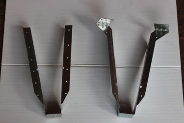
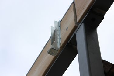
Detail: Locating joist hanger support brackets
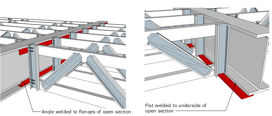
Detail: Alternatives to using joist hanger support brackets
Insert 2 x 12-14x20 hex head fasteners into both the top and bottom chords at support bracket locations. 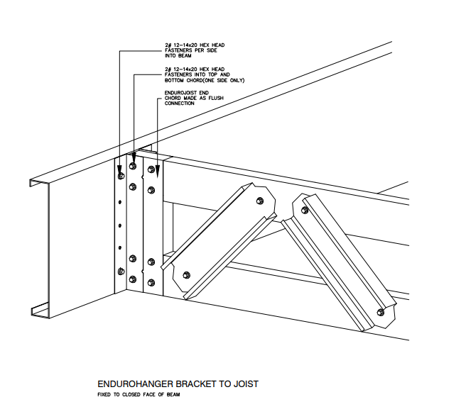
Lift secondary support beams into position and fix in place as specified (Note: connection to be specified by suitably qualified engineer or manufacturer).
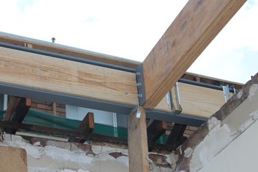
Picture: Fixing Secondary support beams
Install connection brackets to secondary support trimming beams for floor trusses (Note: connection to be specified by suitably qualified engineer or manufacturer).
Independent wall to floor system
You can use the independent wall to floor system to create intermediate floor cassettes comprised of the intermediate floor joists and two shorter end walls called dwarf walls. Each cassette can be assembled on-site or pre-assembled and transported as a single block.
.png?version=1&modificationDate=1515985577876&cacheVersion=1&api=v2&width=685&height=400)
Note
You can opt to use the independent wall to floor system by selecting Independent in the Floor to Wall field of the Detailing options window. See /wiki/spaces/EH/pages/96489886.
Assembling independent floors on-site
To assemble an independent floor on site:
Place the bottom plates of the end dwarf walls into position on top of the lower storey support walls as shown by the highlighted lines below.
.png?version=1&modificationDate=1515986535777&cacheVersion=1&api=v2&width=339&height=250)
Note
Record the location of the side flange notches that have been added to accommodate for the floor truss and supporting beam positions.
Fix the bottom plates of the end dwarf walls to the top plate of the lower storey support walls using 1 x 12-14x20 hex head fasteners on either side of the dwarf stud.
Note
Dwarf end walls can be delivered to on site as pre-fabricated panels. When this occurs you should to remove the top plate of the dwarf wall prior to fixing.
Lift primary support beams into place as indicated on the layout drawing.
Note
You may need to add packers to support beams to ensure the appropriate height or location is achieved. Packers may be placed to the underside, top or face of the beam to set the correct location and level of the beam for fixing off the floor trusses. See Connecting joists to beams.
Install end dwarf studs into their correct locations and fix with 1 x Walltite® screw to both flanges of the bottom plate.
Note
This step is omitted when the end dwarf walls are pre-fabricated.
Lift floor trusses into place, ensuring that the toes of the chord face away from the dwarf studs as shown below.
- Fix the the top and bottom chords of each floor truss to its corresponding dwarf wall studs using 1 x Trusstite® at the pre-punched hole locations.
Add 2 re-inforcing screws for a total of 3 screws to connect the top chord, and a total of 3 screws to connect the bottom chord.
Place angle stud (roll-over restraint) at the locations defined in the layout sheet and fix to each side of the bottom plate using single Walltite® screws.
Important
Maximum angle stud spacing is 1800mm c/c.
Place the top plate of the dwarf end walls into position to cap the top chords of the floor trusses and dwarf studs.
Note
Some adjustment of the floor components and dwarf studs may be necessary.
- Fix all dwarf studs and angle studs (roll-over restraints) in place with 1 x Walltite® screw to both the inside and outside of the top plate.
- Select the appropriate tiedown from Detail A and C at A-32x1.0mmstrapfixedwithmin2x12-14x20mmscrewstoeachend, C-200x25x3mmHDstraptie-downfixedwithmin6x12-14x20mmscrews to connect upper walls to lower walls.
- Install ceiling battens into place as indicated on the layout drawings. See Ceiling battens and plasterboard angles.
.png?version=2&modificationDate=1515990254811&cacheVersion=1&api=v2&width=516&height=250)
Install structural flooring per the manufacturer's recommendation or as specified in AS1860: Installation of particleboard flooring.
.png?version=2&modificationDate=1515990715246&cacheVersion=1&api=v2&width=514&height=250)
Important
You must ensure the flooring used is suitable for the loading conditions and truss spacings.
Note
Feature strip flooring is not suitable for fixing directly to the top chords of ENDUROFLOOR™ trusses. We recommend that a sheet floor is installed as a structural layer with strip flooring then being installed on the top surface as a decorative layer to AS1684.
Pre-assembling independent floors
Pre-assembling independent floors is very similar to on-site assembly. The difference is that because the floor is pre-assembled then delivered as a single block as shown below. This requires the installation of lifting hardware and a specialist lifting team.
To pre-assemble an independent floor:
Place the relevant dwarf end wall bottom plates onto the fabrication table.
Note
Record the location of the side flange notches that have been added to accommodate for the floor truss and supporting beam positions.
Place primary support beams as indicated on the layout drawing, if required.
Note
You may need to add packers to support beams to ensure the appropriate height or location is achieved. Packers may be placed to the underside, top or face of the beam to set the correct location and level of the beam for fixing off the floor trusses. See Connecting joists to beams.
Install connection brackets to primary support beams for all secondary support trimming beams and floor trusses, if required.
Important
Connections must be specified by a suitably qualified engineer.
Place secondary support beams into position and fix in place as specified.
Important
Connections must be specified by a suitably qualified engineer.
Install connection brackets to secondary support trimming beams for floor trusses (Note: connection to be specified by suitably qualified engineer).
Important
Connections must be specified by a suitably qualified engineer.
- Install dwarf studs into their correct locations and fix with 1 x Walltite® screw to the inside and outside of the bottom plate.
- Lift floor trusses into place, ensuring that the toes of the chord face away from the dwarf studs as shown below.
- Fix the top and bottom chords of each floor truss to its corresponding dwarf wall studs using 1 x Trusstite® at the pre-punched hole locations.
Add 2 reinforcing screws for a total of 3 screws to connect the top chord, and a total of 3 screws to connect the bottom chord.
Note
The number of reinforcing screws will be the same as that provided for vertical end web.
Place angle stud (roll-over restraint) at the locations defined in the layout sheet and fix to each side of the bottom plate using single Walltite® screws.
.PNG?version=1&modificationDate=1515992527155&cacheVersion=1&api=v2)
Important
Maximum angle stud spacing is 1800mm c/c.
Place the top plate of the dwarf end walls into position to cap the top chords of the floor trusses and dwarf studs.
Note
Some adjustment of the floor components and dwarf studs may be necessary.
- Fix all dwarf studs and angle studs (roll-over restraints) in place with 1 x Walltite® screw to both the inside and outside of the top plate
- Install lifting hardware as specified.
Install structural flooring per the manufacturer's recommendation or as specified in AS1860:2: Installation of particleboard flooring.
Important
You must ensure the flooring used is suitable for the loading conditions and truss spacings.
Note
Feature strip flooring is not suitable for fixing directly to the top chords of ENDUROFLOOR™ trusses. We recommend that a sheet floor is installed as a structural layer with strip flooring then being installed on the top surface as a decorative layer to AS1684.
- Check the dimensions of structural supports on site for compliance with floor truss layout to enable correct fitting.
- Check panel size on site for correct fitting prior to lifting into position.
- With the assistance of a specialist lifting team, safely lift floor panel into position and connect upper walls to lower walls following detail A and C at A-32x1.0mmstrapfixedwithmin2x12-14x20mmscrewstoeachend, C-200x25x3mmHDstraptie-downfixedwithmin6x12-14x20mmscrews
- Install ceiling battens into place as indicated on the layout drawings. See Ceiling battens and plasterboard angles.
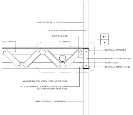
Integrated wall to floor system
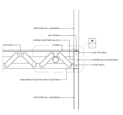
You can use the integrated wall to floor system to create floors using walls that have integrated locations for intermediate floor joists. This method is best suited to full on-site installation as the support walls provide an integral support and restraint for the floor trusses at the supporting wall location.
Note
You can opt to use the integrated wall to floor system by selecting Integrated in the Floor to Wall field of the Detailing options window. See /wiki/spaces/EH/pages/2916868.
To assemble an integrated floor:
- Remove the top plates from the supporting walls using an appropriate driver tip and carefully place them aside for later re-use.
Lift primary support beams into place as indicated on the layout drawing.
Note
You may need to add packers to support beams to ensure the appropriate height or location is achieved. Packers may be placed to the underside, top or face of the beam to set the correct location and level of the beam for fixing off the floor trusses. See Connecting joists to beams.
Install connection brackets to primary support beams for all secondary support trimming beams and floor trusses.
Important
Connections must be specified by a suitably qualified engineer.
Lift secondary support beams into position and fix in place as specified.
Important
Connections must be specified by a suitably qualified engineer.
- Install connection brackets to secondary support trimming beams for floor trusses.
- Lift floor trusses into place taking note of the direction of the truss in relation to toes left/right and up/down and correct location for fixing to the side of extended wall studs. (Ref item: 3)
Fix floor trusses to side of extended wall studs at the pre-punched hole location with 1 x Trusstite® per hole.
- Add 2 re-inforcing screws for a total of 3 screws to connect the top chord, and a total of 3 screws to connect the bottom chord.
Note
Where a balcony step down is present, the vertical chord on the floor truss is to be removed, with the extended wall studs being used in this position. The vertical chords have been installed for transportation and installation purposes only.
- Install any extra fixing screws at floor truss to extended wall stud junction as specified.
- Place top plate into position.
Note
Some minor adjustment of the floor components and extended studs may be necessary.
- Fix all extended wall studs in place with 1 x Walltite® screw to both the inside and outside of the top plate.
- Install ceiling battens into place as indicated on the layout drawings. See Ceiling battens and plasterboard angles.
Install structural flooring to manufacturers recommendation or AS1860.2. Ensure the flooring used is suitable for the loading conditions and truss spacings.
Note
Feature strip flooring is not suitable for fixing directly to the top chords of ENDUROFLOOR™ trusses. We recommend that a sheet floor is installed as a structural layer with strip flooring then being installed on the top surface as a decorative layer to AS1684.
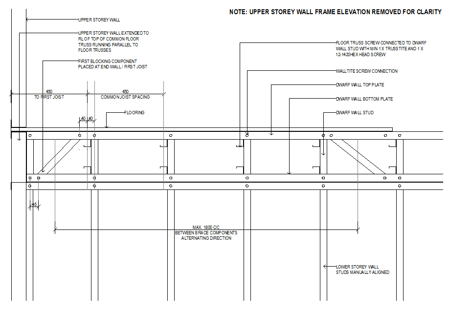
Joist Rollover Restraints
Joists need to be restrained above load bearing walls to prevent the joists from rolling over. These are required where the detailer has selected 'wall none' as the detailing option and the joists are sitting directly on top of the load bearing wall.
Joists connected to integrated or independent walls do not require any additional rollover restraints as the joists are restrained by either studs in the case of integrated walls, or by diagonal bracing studs in the case of independent walls.
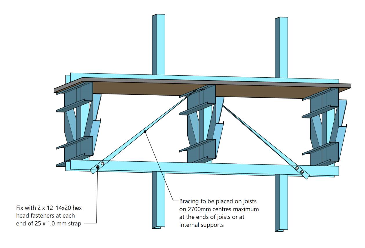
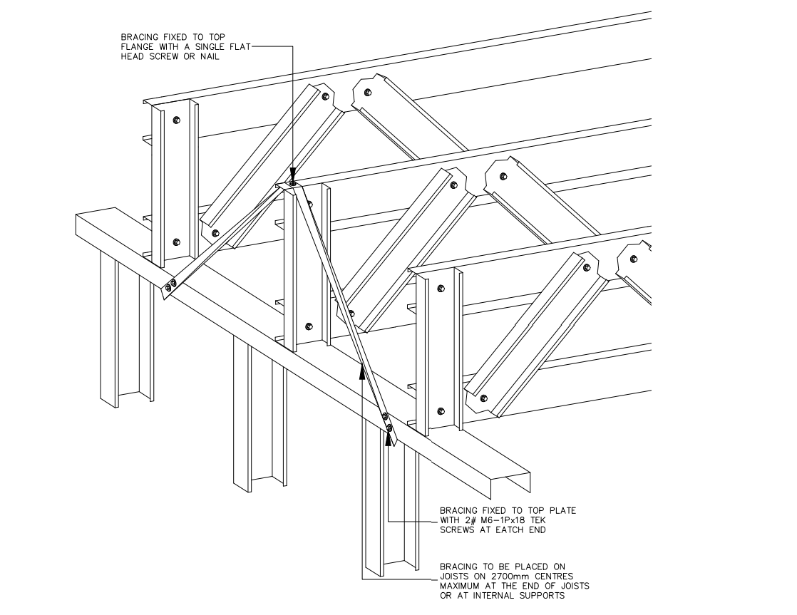
Diagonal bracing
Diagonal bracing can be applied either at the end of joists or where the mid-point of joists sit on load bearing walls. A minimum 25x1.0mm strap is placed over the joist and fixed to the top plate before adjacent floor trusses. A single flat head screw or nail should fix the bracing to the to flange of the joist, and 2 x 12-14x20 hex head screws should tie the strap to the top plate of the wall. Diagonal bracing should be applied to joists no further than 2700mm apart.
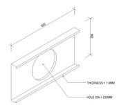
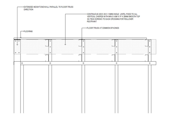
End wall lintel
The end wall lintel system is a simple method of construction where common floor trusses with vertical and horizontal webs are placed onto a supporting wall and beam system. Rollover restraint is accommodated by the installation of a 200x35x1.5mm angle lintel as commonly used in the ENDUROWALL® system. This can only be used at the end of joists.
Where a lintel is specified to be installed at the end of floor trusses, fix in place with 3 x 12-14 x 20mm Hex Head self drilling screws through the face of the lintel into the vertical chord of the floor trusses.
Step 1: Mark position of all floor components as indicated on the layout drawing.
Step 2: Lift primary support beams into place as indicated on the layout drawing. If necessary, pack to appropriate height as required.
Step 3: Install connection brackets to primary support beams for all secondary support trimming beams and floor trusses (Note: Connection to be specified by suitably qualified engineer).
Step 4: Lift secondary support beams into position and fix in place as specified (Note: Connection to be specified by suitably qualified engineer).
Step 5: Install connection brackets to secondary support trimming beams for floor trusses (Note: Connection to be specified by suitably qualified engineer).
Step 6: Lift floor trusses into place taking note of the direction of the truss in relation to toes left/right and up/down.
Step 7: Fix floor trusses to top plate at the correct locations with 1 x 12-14 x 20mm hex head self drilling screw. Alternative tie down types may be specified and should also be fixed at this stage.
Step 8: Once floor trusses are in position, place angle lintel into position. Some minor moving of the floor components may be necessary to facilitate correct location.
Step 9: Check plumb of floor components and once correct, install 3 x 12-14 x 20mm Hex Head self drilling screws through the face of the lintel into the vertical chord of the floor trusses.
Step 10: Install ceiling battens into place as indicated on the layout drawings (Refer: Ceiling battens and plasterboard angles)
Step 11: Install structural flooring to manufacturers recommendation or AS1860.2. Ensure the flooring used is suitable for the loading conditions and truss spacings.
Note: Feature strip flooring is not suitable for fixing directly to the top chords of ENDUROFLOOR™ trusses. It is recommended that a sheet floor is installed as a structural layer first with strip flooring being installed on the top surface as a decorative layer to AS1684.
Ensure that a screw is located at the cross-over point of the flooring, angle lintel and the floor truss top chord flange.
Ceiling battens and plasterboard angles
As indicated in the floor construction steps, ceiling battens must be fitted immediately after the floor trusses have been installed. By fixing the ceiling battens at this stage the floor trusses will be laterally restrained without the need of bottom chord ties.
Ceiling Battens as Bottom Chord Restraints
Step 1: When all floor trusses are installed, install ceiling battens to the underside of the bottom chords. Ceiling battens can be spaced at 600mm centres or 450mm centres depending on the type of plasterboard that will be used for the ceiling (check the plasterboard manufacturers specifications). Ceiling batten sizes shall be selected from batten manufacturer's technical literature and sized to suit span, spacings and loads.
NOTE: Ceiling battens spacing is dependent on ceiling lining. For suspended ceilings, lateral restraints must be provided at spacings specified Floor Truss Layout Sheet.
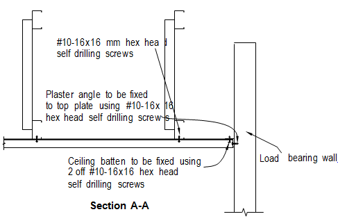
Step 2: Fix the ceiling battens with two #10-16x16mm hex head self drilling screws, one into each flange of the batten into the bottom chord of the floor truss.
Step 3: Plasterboard angle must be used at the intersection of the ceiling batten/load bearing wall junction to support the ends of the ceiling battens.
Internal wall support and shear transfer
It is important that the truss can move up and down in this bracket so screws should be able to slide. To enable the trusses to slide ensure the fastener is placed in the middle of the slot and it is not over tightened.
For shear transfer, refer to Wall Installation manual.
Step 1: Fix one #10-16x16mm hex head self drilling screw down through the top of the bracket and into the top of the ceiling batten to stop the bracket sliding.
Step 2: Bend the bracket down to the top plate of the internal wall and fix two #10-16x16mm hex head self drilling screws through the foot of the bracket into the top plate.
Step 3: Install hitch brackets to the bottom chord of floor trusses at a maximum of 1200mm centres. Fix two #10-16x16mm hex head self drilling screws into the side of the flat face of the bottom chord.
Step 4: Fix two #10-16x16mm hex head self drilling screws through the foot of the bracket into the top plate.
Floor Joist Penetrations
Maximum Hole Penetration Size through Joists
The maximum size of penetrations that can fit through various joist sizes are as follows:-
| Floor Truss Depth | Chord Section | Max. round penetration diameter | Penetration area (mm3) |
|---|---|---|---|
250mm | C75 | 100mm | 7854 |
| C90 | 70mm | 3848 | |
| 300mm | C75 | 150mm | 17671 |
| C90 | 120mm | 11310 | |
| 350mm | C75 | 200mm | 31416 |
| C90 | 170mm | 22698 | |
| 400mm | C75 | 250mm | 49087 |
| C90 | 220mm | 38013 |
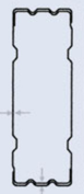
The gap - A - measured below is 60mm for floors made with the C90 system and 70mm for floors made with C75 sections.
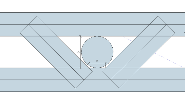
Maximum dimensions of services within floor joists
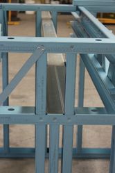
220mm Penetrations with SFS Stiffening Section
Where a penetration up to 220mm is required to be inserted in either a 300mm or 350mm deep joist is required an SFS 300mm deep joist made from 1.9mm (BMT) material with a 220mm diameter preformed hole can be used. When used in a 300mm deep floor joist the stiffening part shall be 600mm long and be installed in its horizontal axis and shall replace 2 truss webs. For 350mm deep joists, the part shall be 350mm long and be installed in its vertical axis and replace a single truss web.
Penetrations can only be inserted in the middle third of the floor truss span, and shall not be provided around internal supports.
The SFS accessory shall be fixed with 16 x 12-14x20 hex head fasteners following the screw pattern indicated below. The chords on the trusses can be notched out to follow the profile of the penetration, and can be cut with either tin snips or a plasma cutter.
Inserting 220mm diameter stiffener parts
Where larger openings are required, joists shall be inserted to run parallel with the penetration.
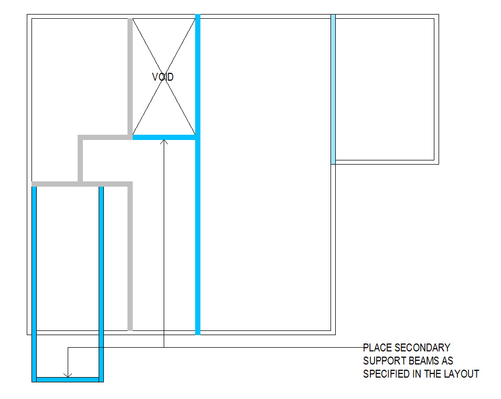
Installing beams around stair voids
The following generic installation method may be used for stair voids where the following design loads apply to the floor:-
Floor load
- 0.6kN/m2 Dead Load
- 1.5kN/m2 Live load
Stair Load
0.6 kN/m2 Dead load
2.0 kN/m2 Live load
The serviceability is span/400 or 12 mm for dead load + 70% live load.
Please consult an engineer for the design of beams outside these design loads.
In order to determine the size of the beams to be used, the following information must be determined:-
- the ENDUROJOIST shortened span. This is the distance the ENDUROJOIST spans and lands on Header Beam A.
- the span of Header Beam A. This is the span of the beam the incoming ENDUROJOIST spans are connected to. Beam A may connect to either another beam or a load bearing wall.
- the span of Beam B. This is the span of the beam that Header Beam A connects to.
- the location of Beam A on Beam B.
Refer to to the figure below for a diagramatic representation of respective beams and spans.
ENDUROFLOOR Stair Trimmer Plan Layout

Refer to the ENDUROFLOOR Design Manual for beam dimensions and maximum spans. Please consultant with your ENDUROFLOOR manufacturer if you cannot access these span charts. The connection details to connect beams together is shown below.
Stair Void Beam Layout Assembly Diagram
The connection details to join beams together are shown in the diagram below.
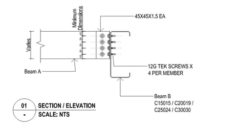
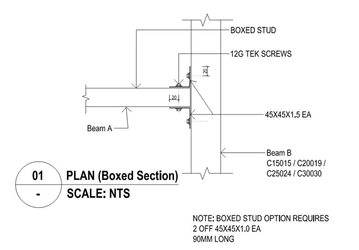
Stair Void Beam connection details
Temporary Construction Bracing and Material Loads Positioning
All floor trusses are to be temporarily braced prior to the installation of flooring material. This will ensure the frame remains square, floor trusses are in place and plumb.
Loads from heavy materials such as packs of flooring are to be placed over lines of support such as internal loadbearing walls under, or near external load bearing walls. Loads are not to be placed at mid-span of floor trusses.
