5.0 Frame assembly
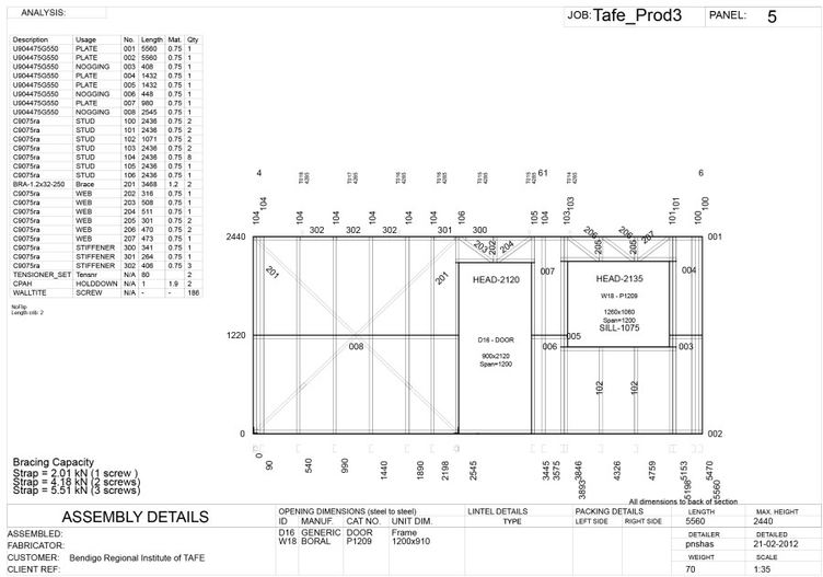
Wall frame assembly sheets are produced by the ENDUROCADD® software during the detailing process. Below is an example of a typical wall frame assembly sheet produced by ENDUROCADD®.
5.1 Print string markings
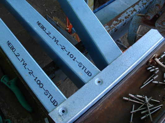
All ENDUROWALL® parts are marked with coded print strings to assist erectors during the assembly process. This matches the part information shown on the assembly drawings. Parts are coded in the following order:
- Job Id
- Frame Number
- Part Number
Part Usage.
Note
For short parts, some of this information is deleted.
With this information, erectors can identify what the part is and where it is intended to be used in the structure.

Using Figure 6.1 we can determine:
- Job id is Test_walls
- Wall panel number is 5
- Part number is 001
- Part is to be used for the TOPPLATE.
Newer walls have a usage identifier rather than the full usage description and may have additional information such as the part length. You can easily identify the usage using the following table:
| Identifier | Usage |
|---|---|
| TP | Top Plate |
| BP | Bottom Plate |
| HEAD | Header |
| SILL | Sill |
| STUD | Stud |
| NOGG | Nogging |
5.2 Assembly procedure
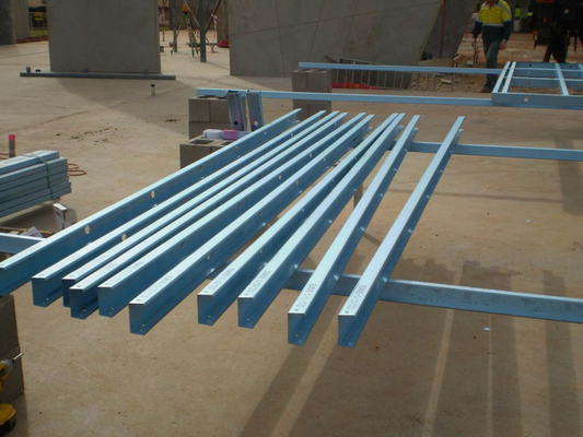
ENDUROWALL® frames are generally factory assembled or assembled by third-parties from completely knocked down (CKD) packs.
It is important that you check all components delivered on-site against your delivery packing list to ensure complete delivery. Unpack and sort the frames into frame lots using the branding as a manual. Identify the studs from the branding information on the parts.
Step 1
Identify and lay the studs toes down on a level surface and align as per assembly drawing. The heads, sills and noggings should be pre-notched to allow parts to overlap as shown, however, certain nogging sections with double or triple web punches may have a web section still connected to improve the roll forming efficiency. See section 2a Prepare Noggings and U sections. Pre-punched holes are provided for trilobular fastener screws to connect the frames.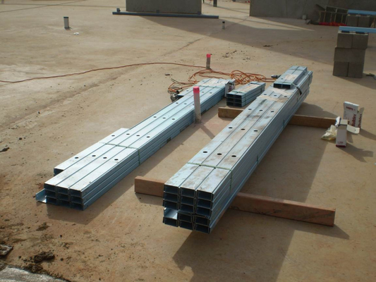
Locate and open matching stud and nogging / plate bundles before separating into individual frame packs.
Separate and move stud and nogging / plate frame packs next to designated assembly zone.
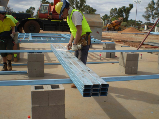
Lift and separate stud pack onto assembly table (this example has utilised Topspan® 40 sections on concrete block stacks as an assembly table).
Step 2 - Prepare bent tab studs
Identify and separate Endurotie® bent tab studs (90mm system only). The Endurotie® bent tab studs can be identified by the extension of the stud web section and double15mm hole punch for insertion of a frame anchor bolt (or similar).
- Place the stud with the web down.
- With a small cold chisel and a hammer, flatten the ribs on the rib in line with the stud flange.
- With a pair of duck bill pliers, bend the tab in the appropriate direction. (Refer to layout plan provided with job outputs.)
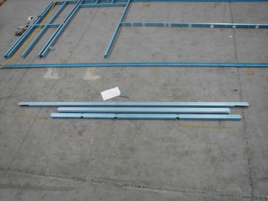
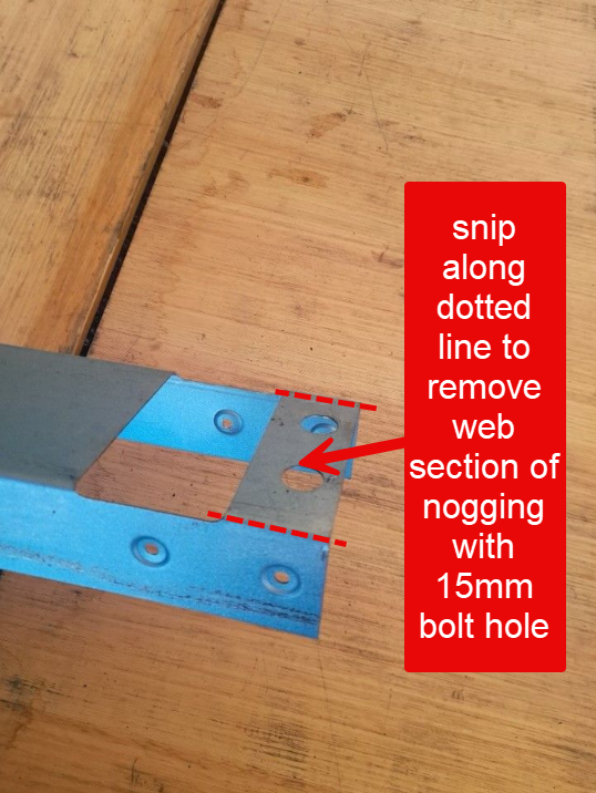
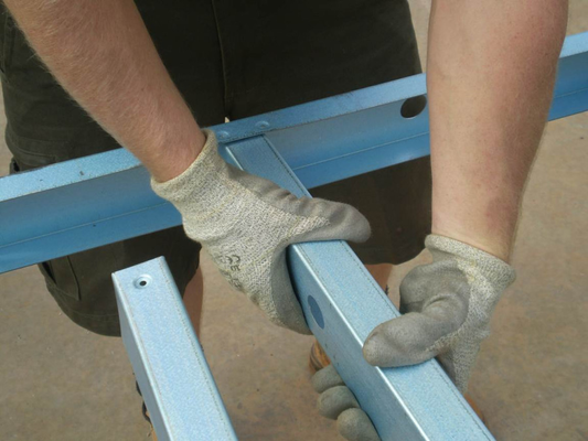
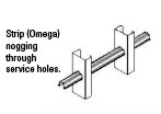
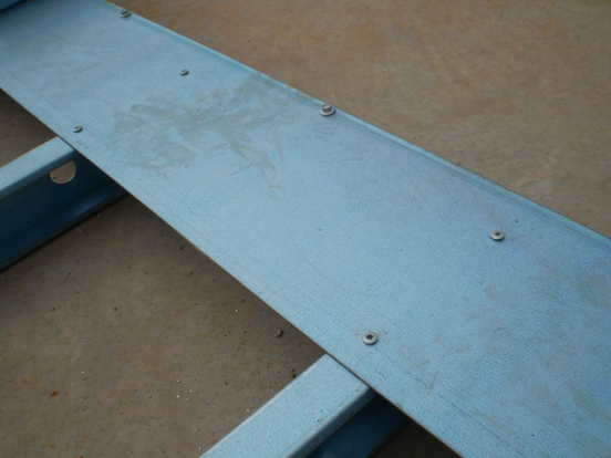
Step 2a - Prepare Noggings and U-Sections
With the noggings and plate sections separated into their individual wall numbers, check each U section for any double 15mm bolt hole punches (see below picture). This punch represents a web section of the nogging to be cut out on site prior to wall fabrication using tin snips or a suitable cutting tool. Note that ONLY the web section of the plate needs to be removed, the flanges of the u section are to remain connected.
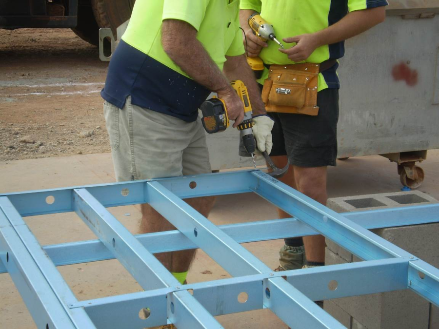
Step 3: Lay out studs and insert into top and bottom plates
Layout all studs in sequential order, space out & orientate frame as per assembly sheet.
Fix all studs by inserting into top plate on approx. 45deg angle.
Align holes, fix at studs and install trilobular fastener.
Step 4 - Fix at Studs
When carrying out the primary assembly of the frame align notch holes as shown and install trilobular fastener in holes.
Align top of studs & screw fix top plate at both ends. (Where utilised, ensure Endurotie® bent tab studs are placed in the correct location and orientation. 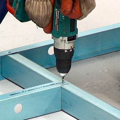
Twist stud into position & align fixing holes – repeat for all studs along top plate.
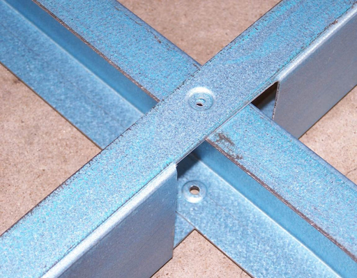
Step 5 - Fix at corner and install trilobular fastener
Align notch holes as shown and install trilobular fastener in holes. 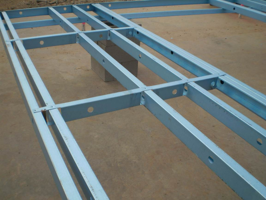
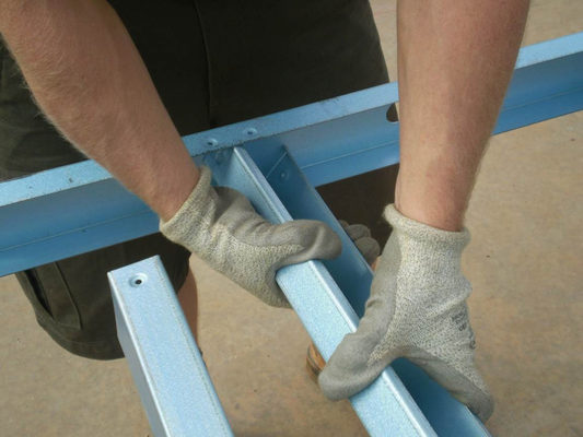
Slide noggings onto the studs from base of frame & align fixing holes. May require 2 people to slide up studs evenly.
Fix bottom plate to studs, align holes & screw fix all noggings & bottom plate connections on "Side A". (Easier to fix bottom plate on an angle, starting at one end & pinching studs into plate, working along the frame). Ensure Endurotie® bent tab stud alignment is correct.
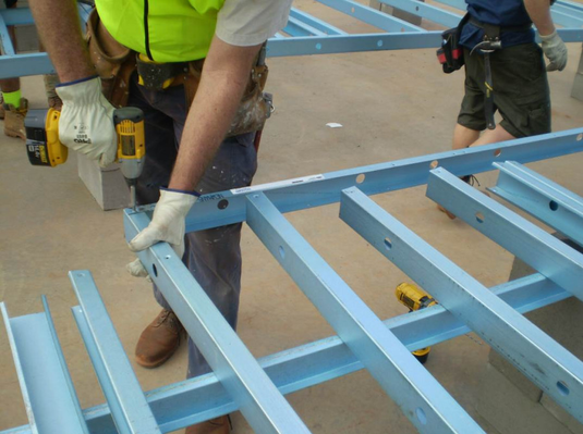
Step 6 - Install Noggings
Position each one over the frame near their final location. Nogging height is specified in the supplied ENDUROCADD® panel drawings with the reference line to the centre line of the nogging. 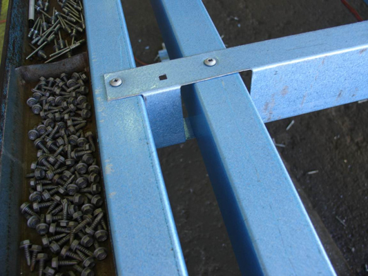
Nogging installation.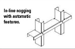
Step 7 - Fix both sides
In order to process walls efficiently, two assembly tables situated side-by-side allows walls to be flipped over so both sides can be fixed off. 
Cross check "Side A" frame layout & connections as per assembly sheet. Utilizing sufficient labour, lift & flip frame for "Side B" screw fixings.
Ensure sufficient labour available on both sides of frame to flip safely.
By utilizing two adjoining assembly tables, wall fabrication can be optimized by preparing the next frame while screw fixing and checking "Side B".
Step 8 - Marking wall frames and prepare for openings
Before inserting any bracing or lintels, check the overall dimensions of the frame against the supplied Assembly Sheet. Square the frame before installing any bracing. Frames should be identified with panel number and the number of any adjoining walls at the appropriate locations. These marks should be applied to the side of the bottom plate. 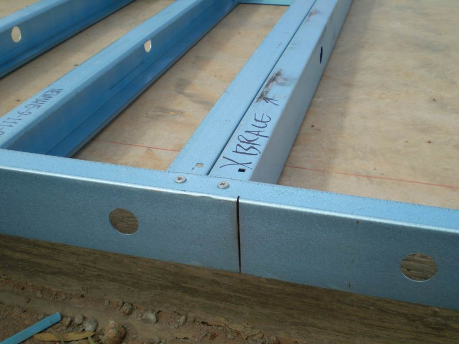
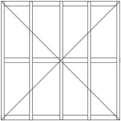
Step 9 - Install Cross Bracing
Install cross bracing as per wall assembly sheet using the nominated number of screws. Number each completed wall frame and mark the bracing locations to top & base of frames as per assembly sheet.
Locate the pre-cut notch and use tin snips to prepare the tab prior to installation. (This enables easy removal of bottom plate at openings after frame installation). After panel is checked for squareness, screw fix bracing strap to wall plates as per wall frame assembly sheet. Alternate bracing types are fixed in a similar manner.
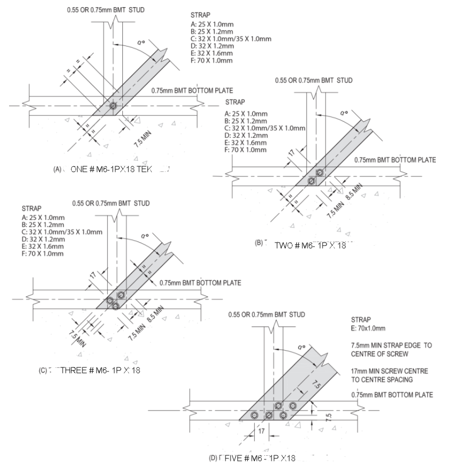
Figure 6.3 - Connection details of diagonal tension strap bracing
70mm strap brace requires two tensioners.
Step 10 - Install lintel (where required)
Fixing Angle Lintel
Overlay and screw fix lintel flashing to top of frame as per assembly sheet and fixing details given in the Design Manual.
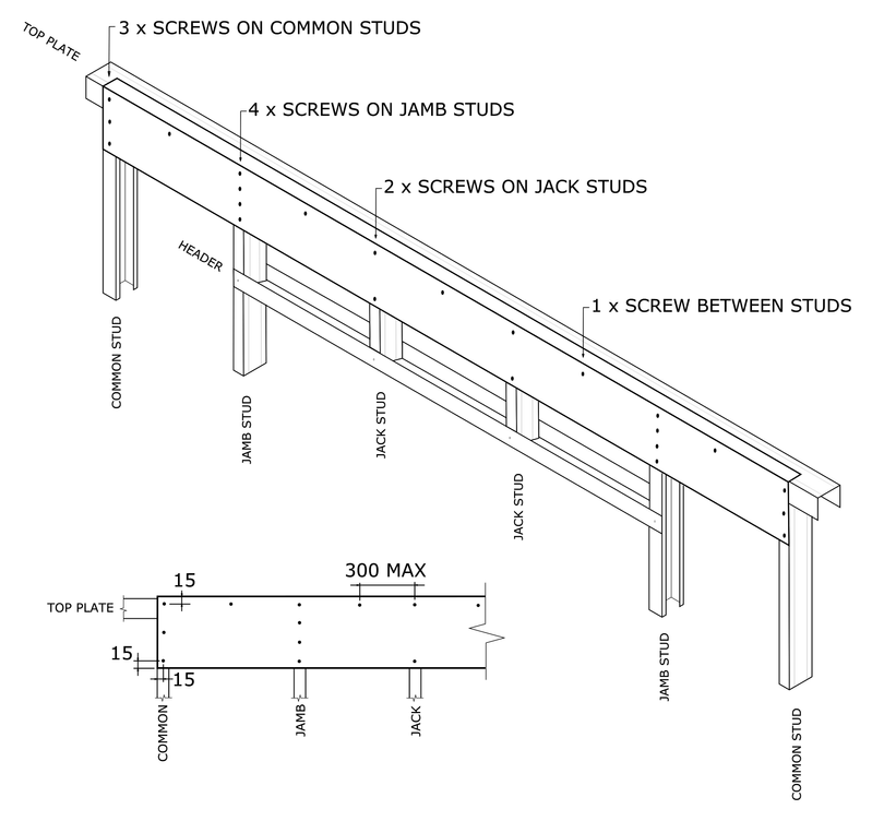
- Jack Stud and Jamb Stud must be secured to the header with 1 x FRAME SCREW at each connection.
- Jack Studs must be secured to the top plate with 1 x FRAME SCREW at each connection.
- Check which faces lintel is to be secured (Internal, External or both).
- Secure lintel to frame to face(s) with 1 x TEKS SCREW in position as shown on diagram.
| Minimum Construction Requirements | |
|---|---|
| FRAME SCREW | M6 Frame Screw |
| TEKS SCREW | M6 GX Teks Smooth Top |
| TOP PLATE | 0.75mm BMT G550 Plate |
| HEADER | 0.75mm BMT G550 Plate |
| JACK STUDS | 0.55mm/0.75mm BMT G550 Ribbed Cee Studs |
| LINTEL | 200mm x 35mm x 1.5mm BMT G450 Angle Lintel |
| JAMB STUDS | 0.75mm BMT G550 Ribbed Cee Studs |
For sheet roof from 15° up to 30°, with truss spacing up to 1200mm. For other scenarios, check with designer for appropriate detail drawing.
Detail applies to upper story or single story only. For other scenarios, check with designer for appropriate detail drawing.
Fixing ENDUROFRAME Sections or C sections as headers
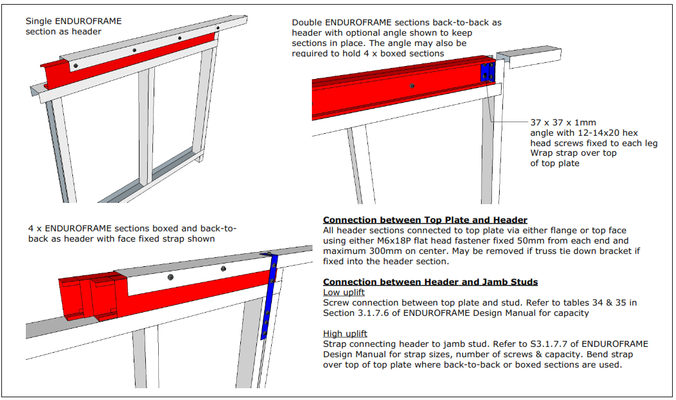
Fixing ENDUROFRAME® sections as headers
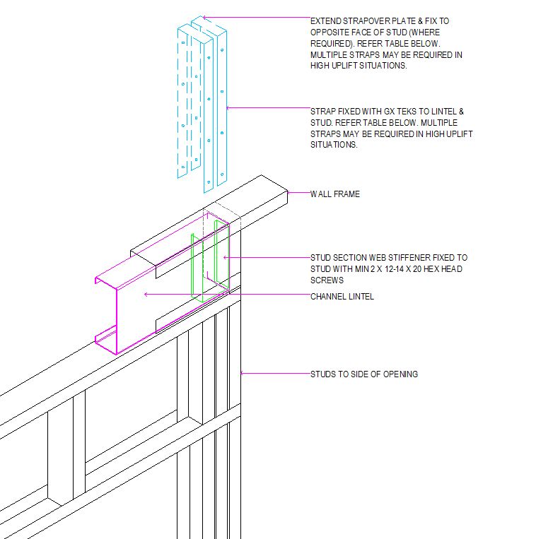
Fixing Channel sections as headers
| Strap Size | Single or Double Sided | Straps | M6 Teks into Header and each Strap | M6 Teks into Jamb Stud and each strap |
|---|---|---|---|---|
| 30mm x 1.0mm | Single | 1 | 2 | 3 |
| 30mm x 1.0mm | Single | 2 | 2 | 3 |
| 50mm x 1.0mm | Single | 1 | 4 | 6 |
| 50mm x 1.0mm | Single | 2 | 4 | 6 |
| 30mm x 1.0mm | Double | 1 | 2 | 6 |
| 30mm x 1.0mm | Double | 2 | 2 | 6 |
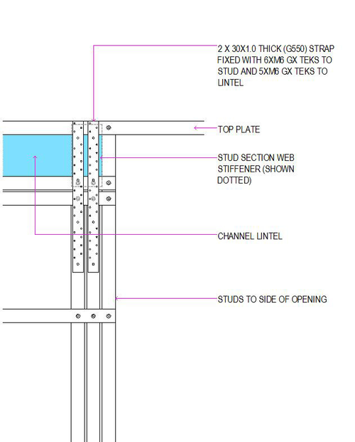
FIGURE 6.17 - Beam Header Fixing Details
Step 11 - Stack completed wall frames before installation
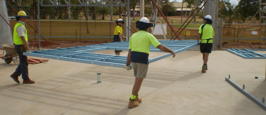
Relocate completed frames to a designated stacking area.
Stack wall frames in bundles close to the final installation position. 
Ensure all wall frame locations have been set out on floor substrate before installation commences. Large wall frames may require additional stiffening to assist stability during installation process.