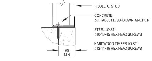
8.0 Typical hold down connections
Nominal Stud Tie-down
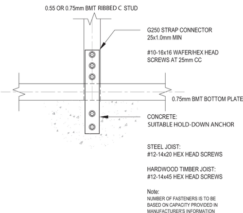
Strap connection options
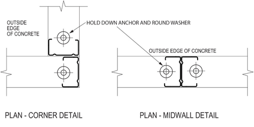
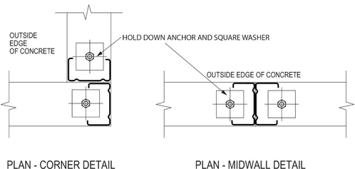
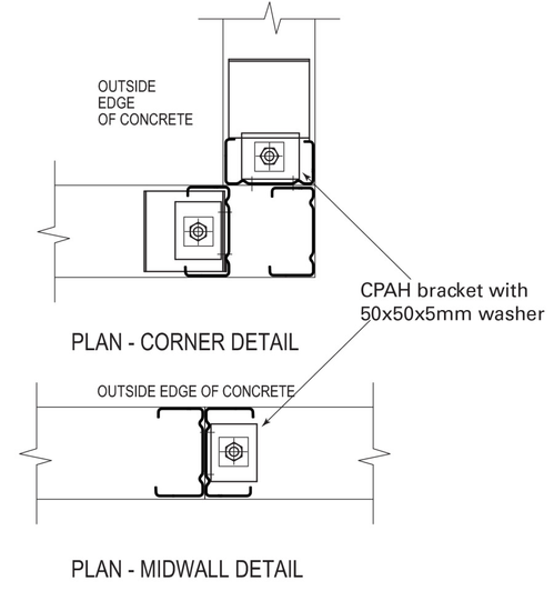
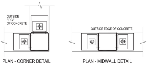
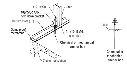
Corner/Mid-wall - Hold-down anchor and round washer
For hold down anchor capacity, refer to manufacturer's information. Suitable hold down anchors are to be provided to resist the uplift forces.
Corner/Mid-wall - Hold-down anchor, bracket and square washer
For hold down anchor capacity, refer to manufacturer's information. Suitable hold down anchors are to be provided to resist the uplift forces.
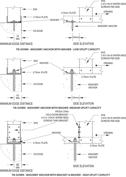
Tie-down - Masonry anchors with washers (low uplift capacity - 4.8kN Limit State)
For hold down anchor capacity, refer to manufacturer's information. Suitable hold down anchors are to be provided to resist the uplift forces defined in Tables 2-5 of Section 3.3.1 of the ENDUROWALL® Building System Design Manual.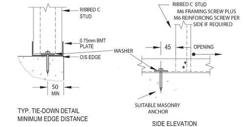
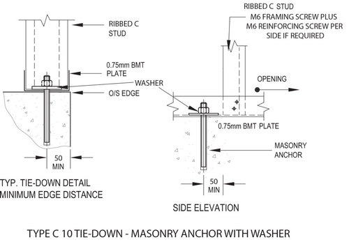
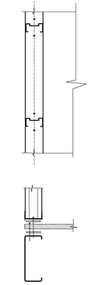
Tie-down - Masonry anchors with washers (medium uplift capacity - 7.5kN Limit State)
For hold down anchor capacity, refer to manufacturer's information. Suitable hold down anchors are to be provided to resist the uplift forces calculated by the ENDUROCADD® software or as defined in Tables 2-5 of Section 3.3.1 of the ENDUROWALL® Building System Design Manual.
Endurotie® bent tab stud tie down
For hold down anchor capacity, refer to manufacturer's information. Suitable hold down anchors are to be provided to resist the uplift forces by the ENDUROCADD® software or as defined in Tables 2-5 of Section 3.3.1 of the ENDUROWALL® Building System Design Manual.

Stud Thickness (mm) | Plate thickness (mm) | 90mm sections | 75mm sections1 | 70mm sections1 | |||
|---|---|---|---|---|---|---|---|
| Uplift capacity with 40x40x5mm2 washer | Uplift capacity with 24mm dia. bolt head or washer | Uplift capacity with 40x40x5mm2 washer | Uplift capacity with 24mm dia. bolt head or washer | Uplift capacity with 40x40x5mm2 washer | Uplift capacity with 24mm dia. bolt head or washer | ||
| 0.75 | 0.75 | 15.0kN | 6.0kN | 9.09kN | 4.0kN | 7.9kN | 3.5kN |
| 1.0 | 1.0 | 21.0kN | 15kN | 18.49kN | 11.25kN | 17kN | 10.3kN |
| 1.2 | 1.2 | 30.0kN | 19kN | N/A | NA | NA | NA |
1 75mm and 70mm sections require the washers to be installed hard up against the web of the stud to ensure direct load transfer from the bent tab to the structure underneath via the bolt
2 40x40x5mm washers may be substituted with 38x38x5mm washers
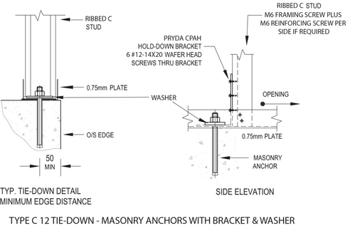
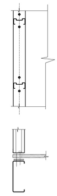
Tie-down - Masonry anchors with bracket and washer (high uplift capacity - 12.5kN Limit State)
For hold down anchor capacity, refer to manufacturer's information. Suitable hold down anchors are to be provided to resist the uplift forces by the ENDUROCADD® software or as defined in Tables 2-5 of Section 3.3.1 of the ENDUROWALL® Building System Design Manual.
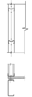
Tie-down - Square Hollow Section (SHS)
For hold down anchor capacity, refer to manufacturer's information. Suitable hold down anchors are to be provided to resist the uplift forces by the ENDUROCADD® software or as defined in Tables 2-5 of Section 3.3.1 of the ENDUROWALL® Building System Design Manual.
Corner/Mid-wall Detail (Low Uplift Capacity)
Corner/Mid-wall Detail (Medium Uplift Capacity)
For hold down anchor capacity, refer to manufacturer's information. Suitable hold down anchors are to be provided to resist the uplift forces by the ENDUROCADD® software or as defined in Tables 2-5 of Section 3.3.1 of the ENDUROWALL® Building System Design Manual.
Corner/Mid-wall Detail (High Uplift Capacity)
For hold down anchor capacity, refer to manufacturer's information. Suitable hold down anchors are to be provided to resist the uplift forces by the ENDUROCADD® software or as defined in Tables 2-5 of Section 3.3.1 of the ENDUROWALL® Building System Design Manual.
Corner/Mid-wall Detail (SHS)
For hold down anchor capacity, refer to manufacturer's information. Suitable hold down anchors are to be provided to resist the uplift forces by the ENDUROCADD® software or as defined in Tables 2-5 of Section 3.3.1 of the ENDUROWALL® Building System Design Manuall.
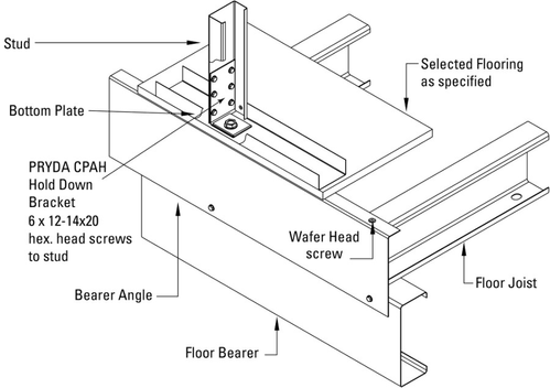
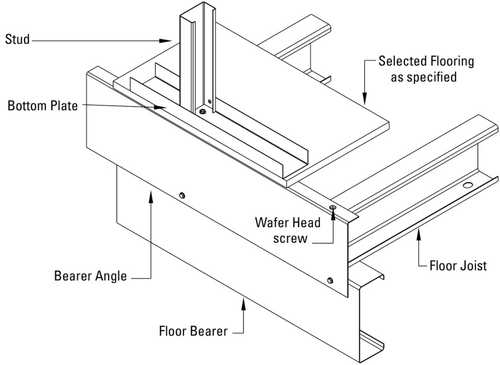
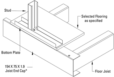
Tie-down into suspended frame floor systems
| Connection Type | Base Material | Fasteners - Particle Board to Joist | Fasteners - Adjacent to Studs | Limit State Load (kN) |
|---|---|---|---|---|
| A | C20015 joist directly under wall | Dia. 3.3 x 5.5mm Duo Fast nails (or equivalent) at 200mm centre to centre | Dia. 3.3 x 5.5mm Duo Fast nails (or equivalent) at one nail each side of stud | 3.62 |
| B | Dia. 3.3 x 5.5mm Duo Fast nails (or equivalent) at 200mm centre to centre | Dia. 3.3 x 5.5mm Duo Fast nails (or equivalent) at one nail each side of stud | 3.88 | |
| C | #10-16x45mm CSK Tek screws of equivalent at 150mm centre to centre | #10-16x45mm CSK Tek screws or equivalent adjacent to each stud | 4.76 | |
| D | Dia. 3.3 x 5.5mm Duo Fast nails (or equivalent) at 200mm centre to centre and Structaflor® elastomeric adhesive | #12-14x45mm Hex. head Tek screws or equivalent one each side of stud | 5.72 | |
| E | Laminated Veneer Lumber or timber with JD4 Joint Group to AS1720 | Min 50 x 2.5mm machine driven nails in accordance with manufacturers recommendations or AS1860 and Structaflor® elastomeric adhesive | M5.5 x 40mm Hex. head batten screws. | 5.71 |
| A | B | C | D |
|---|---|---|---|
| One nail each side of stud through all sections. Nails at 200mm centres through particle board and joist. Adhesive strip at points where particle board meets joists. | One nail each side of stud through all sections. Nails at 200mm centres through particle board and joist. Adhesive strip at points where particle board meets joists and bottom plates. | One screw at each stud; three screws between studs at 600mm centres. Screw through all sections. Adhesive strip at points where particle board meets joists. | One screw each side of stud through all sections. Nails at 200mm centres through particle board and joist. Adhesive strip at points where particle board meets joists. |
|
|
|
|
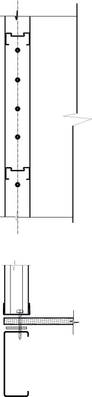
Hold down connection - Option 1
Hold down connection - Option 2
Hold down connection - Option 3
Hold down connection - Option 4
Transfer of Racking Loads to Internal Non-Load Bearing Bracing Walls
There are two different brackets options that may be used for this application: a slotted internal wall wall bracket, or an internal wall bracket. Either option may be used and should be installed at a maximum of 1200mm centers.
Example 1 - Slotted Bracket on Wall Running Parallel to trusses
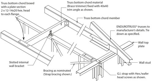
A slotted internal wall bracket shall be fixed to the top plate with 4 x 10-16x16 hex head fasteners and to the truss bottom chord or trimmer with 2 x 10-16x16 hex head fasteners.
It is important that the slots in the bracket allow movement between the truss and wall frame, and the fasteners are not overtightened. The truss should be able to move on the bracket in the event there is settlement. In the event that internal non-load bearing walls run parallel with roof trusses, and trimmer section shall be installed to act as a fixing point for the slotted bracket.
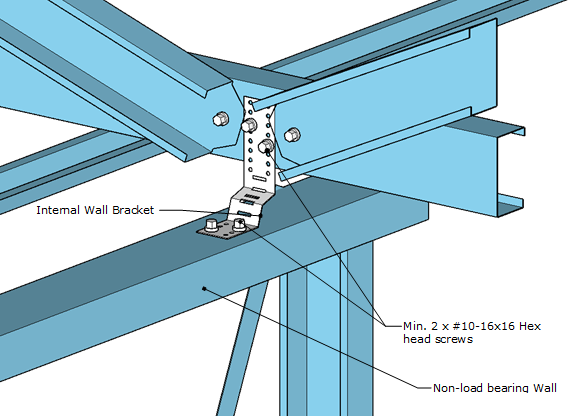
Example 2 - Internal Wall Bracket Perpendicular to Trusses
Example 3 - Internal Wall Bracket Parallel with Trusses
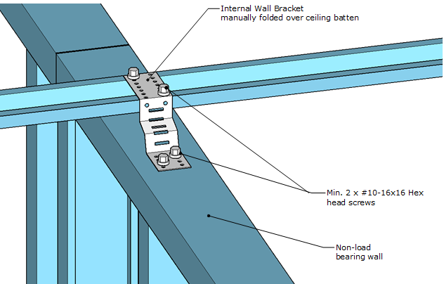
The internal wall brackets can be attached to ceiling battens.
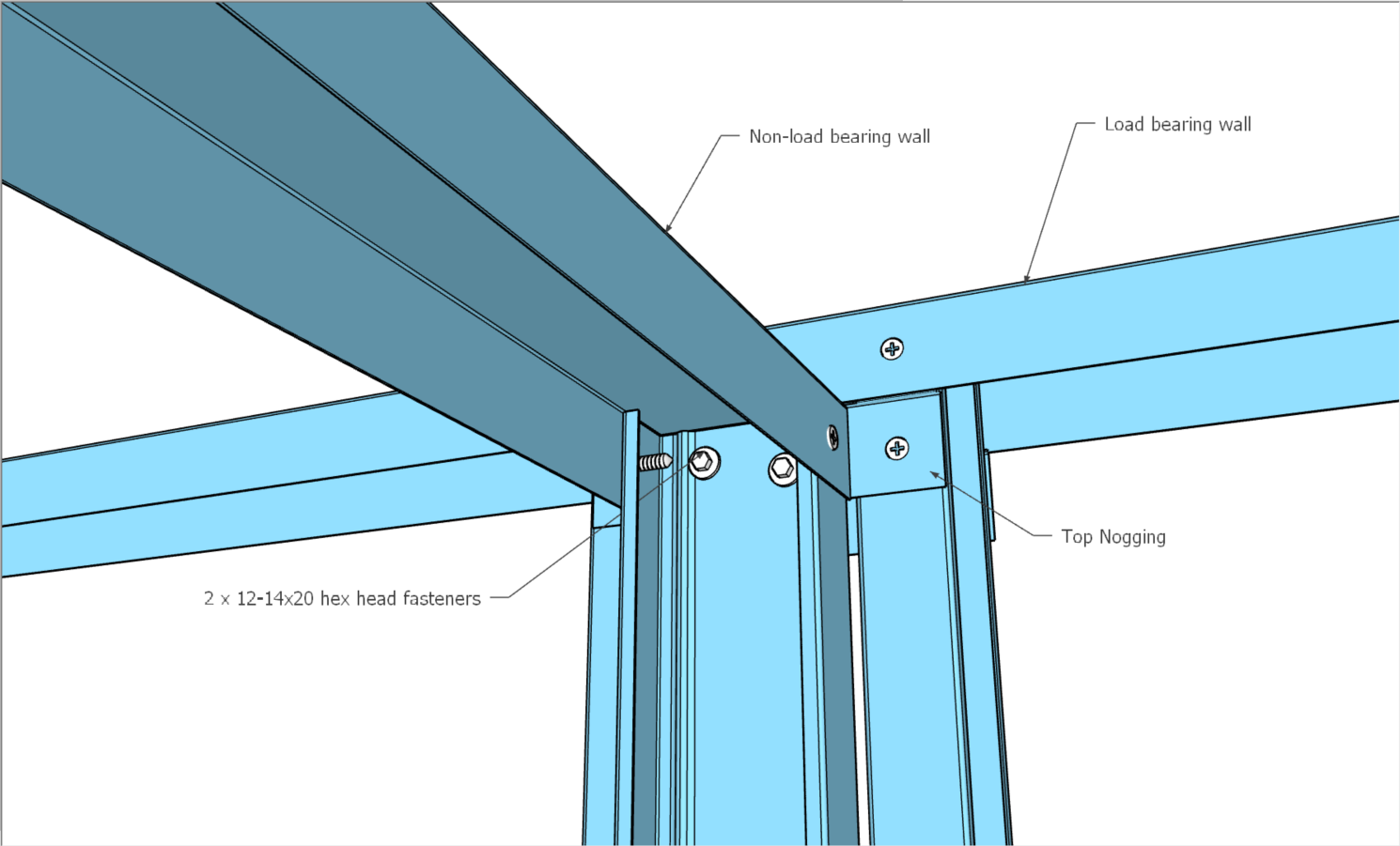
Connecting Non-Load Bearing to Load Bearing Walls
Any of the 3 options below are suitable in non-cyclonic areas.
Option 1 - Strap
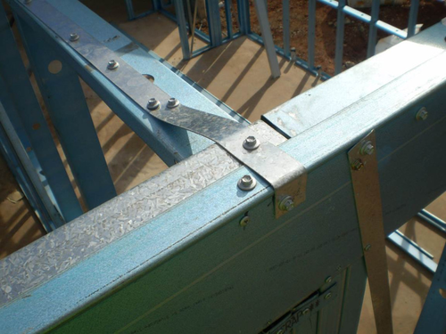
A minimum of 2 x 10-10x16 hex head fasters should be used to connect each end of the 30 x 1.0mm (min) strap. This option is used when there is no top nogging.
Option 2 - Angle
Option 3 - Top nogging