6.0 Wall Construction
ENDUROWALL® wall frames have been designed to engineering standards, but they must be handled, erected and braced correctly to perform as designed. The following recommendations apply to wall frames on standard domestic and light commercial buildings.
Components are selected from the ENDUROFRAME® Building System Design Manual and detailed using the ENDUROCADD® design software to suit the specific roof and floor loads appropriate to the site and architecture. Additional loading such as air conditioning, require special consideration at the time of design and the placing of these additional loads should be referred back to the designer.
Wind load is an important factor in the design and performance of wall frames. Ensure that the correct design wind loads have been used and that the tie down of frames to the floor structure is carried out in accordance with this manual or as specified by the design engineer.
6.1 Prior to construction
The support structure needs to be suitable to build on, make sure to check:
- support structure against the plan dimensions
- plumb and level of the support structure,
- straightness of the supporting walls or beams,
- structure is adequately braced, stable and tied down.
Important
You must rectify the support structure prior to proceeding if it is found to be deficient. Wall frames must be inspected and any damaged parts must be reported immediately to ensure correct rectification. Approval for site rectification should be obtained from the manufacturer.
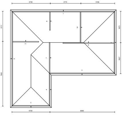
Below is an example of a wall frame layout drawing as generated by the ENDUROCADD® software.
6.1.1 Safety
Ensure that all barriers or scaffolding used in order to comply with safe work practices are installed so as to not damage or overload wall components.
6.1.2 Load bearing wall
The builder should ensure that all loads from both internal and external walls are accommodated in the foundation sub-flooring.
6.1.3 Fasteners
Generally, in non-cylonic wall construction, #10-16x16mm wafer, #10-16x16mm hex head or #12-14x20mm hex head self-drilling Class 3 screws are used for all structural connections. Use the quantity shown on the drawings. In connections, maintain a minimum fastener spacing of 17mm and minimum distance of 17mm to the edge of sections.
6.2 Wall frame setout
Prior to lifting any frames into place, mark out the frame locations on the floor, using the supplied Wall Framing Layout as a reference. Check by measuring diagonals that the marked wall positions are square.
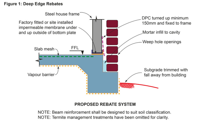
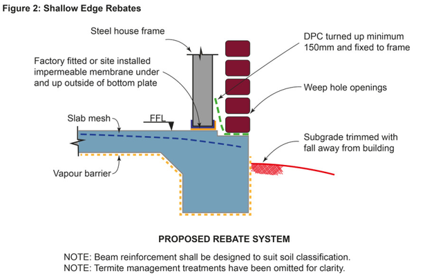
6.3 Damp proof course
You must install moisture impermeable membranes under all perimeter bottom plates fixed to concrete slabs on the ground.
Important
Using moisture impermeable membranes under all perimeter walls is consistent with good building practice and is a condition of BlueScope Steel's warranty on house framing made from TRUECORE® steel. For more information, see BlueScope Steel Technical Bulletin-34.
These membranes should also extend up the weather side flange of the bottom plate because this part of the frame is subject to moist air movement from the lower parts of the cavity as it evaporates and attempts to move past the masonry damp proof course. While it is not considered essential to protect internal bottom plates from moisture, it is best practice is to install impermeable membranes under all interior and exterior bottom plates regardless of conditions.
Suitable impermeable membranes include:
- Bitusik by Grace construction products
- Brushable Hydroseal from Tremco
- Kordon Termite Barrier by Bayer
- Polyethylene and other products specified in BCA Section: Volume 2, 3.3.4.4.
Whilst erecting wall frames ensure that each frame is correctly positioned and orientated to be aligned with the wall slope and plumb (check using a spirit level).
Note
You do not need impermeable membranes when frames are fixed to suspended floors and adequate ventilation is supplied with a minimum distance of 400mm between the underside of the floor framing and the existing ground level. For wet areas refer to AS3740 - 2010: Waterproofing of domestic wet areas.
Tip
The impermeable membrane can be pre-applied to bottom plates at the time of rollforming.